4 connecting the cat 5 twisted pair output, 5 connecting to the vp-31ksi via the rs232 port, 6 connecting to the vp-31ksi via the rs-485 port – Kramer Electronics VP-31KSi User Manual
Page 16: Connecting the cat 5 twisted pair output, Connecting to the vp-31ksi via the rs-232 port, Connecting to the vp-31ksi via the rs-485 port, N 5.6, N 5.5, On 5.6.1
KRAMER: SIMPLE CREATIVE TECHNOLOGY
Connecting the VP-31KSi 3x1 UXGA/Audio STEP-IN Switcher
12
5.4 Connecting the CAT 5 Twisted Pair Output
You can connect the VP-31KSi to any compatible Kramer TP (Twisted Pair)
receiver, for example, TP-120 (no audio) or TP-122/N (with audio).
For further details, refer to the relevant TP receiver user manual
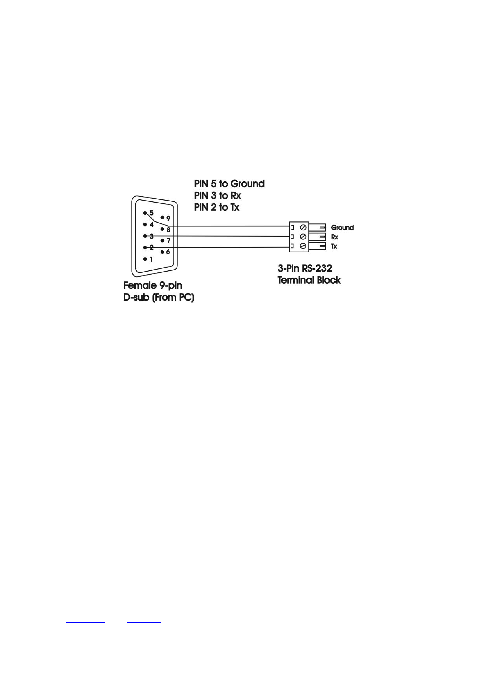
5.5 Connecting to the VP-31KSi via the RS-232 Port
You can connect to the VP-31KSi via an RS-232 connection using, for example, a
PC as shown in
Figure 8: Connecting to the RS-232 Communication Port
To connect to the VP-31KSi via RS-232 as shown in
•
Connect the 3-pin terminal block on the rear panel port of the VP-31KSi
(pin G to pin 5, pin Rx to pin 3, pin Tx to pin 2) to the RS-232 9-pin D-sub
port on your PC
5.6 Connecting to the VP-31KSi via the RS-485 Port
You can operate the VP-31KSi via the RS-485 port from a distance of up to
1200m (3900ft) using any device equipped with an RS-485 port (for example, a
PC). For successful communication, you must set the RS-485 machine number and
bus termination.
To connect a device with a RS-485 port to the VP-31KSi:
•
Connect the A (+) pin on the RS-485 port of the PC to the A (+) pin on the
RS-485 port on the rear panel of the VP-31KSi
•
Connect the B (–) pin on the RS-485 port of the PC to the B (–) pin on the
RS-485 port on the rear panel of the VP-31KSi
•
Connect the G pin on the RS-485 port of the PC to the G pin on the RS-485
port on the rear panel of the VP-31KSi
5.6.1 Setting the RS-485 Machine Number and Bus Termination DIP-switches
This section describes the VP-31KSi DIP-switch settings that determine the
RS-485 machine number and bus termination.