Figure 2: vp-28, Presentation switcher rear panel, Figure 2 – Kramer Electronics VP-28 User Manual
Page 11
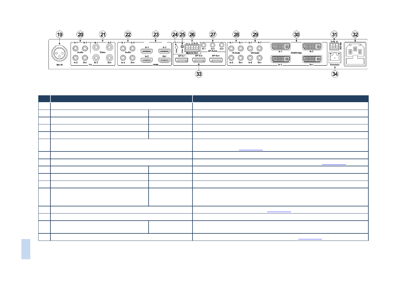
Figure 2: VP-28 Presentation Switcher Rear Panel
#
Feature
Function
19 MIC IN XLR Connector
Connect a microphone.
Note: Only one microphone can be connected at a time
20 CV AUDIO 3.5mm Mini Jack Connectors
IN 1 ~ IN 3, OUT
Connect to the audio channel of the CV sources and acceptor
21 CV VIDEO RCA Connectors
IN 1 ~ IN 3, OUT
Connect to the video channel of the CV sources and acceptor
22 HDMI AUDIO 3.5mm Mini Jack Connectors IN 1 ~ IN 3, OUT
Connect to the audio channel of the HDMI sources and acceptor
23 HDMI VIDEO Connectors
IN 1 ~ IN 3, OUT
Connect to the video channel of the HDMI sources and acceptor
24 RESET Button
Press and hold while turning on the power to the device to reset to factory
default settings (see
Section 6.4
25 PROG Button
For the use of Kramer service personnel only
26 MASTER OUT 5-pin Terminal Block Balanced Audio Output
Connect to the balanced, stereo master audio acceptor (see
Section 5.3
27 DP AUDIO 3.5mm Mini Jack Connectors
IN 1, IN 2, OUT
Connect to the audio channel of the DP sources and acceptor
28 PC AUDIO 3.5mm Mini Jack Connectors
IN 1 ~ IN 3, OUT
Connect to the audio channel of the PC graphics sources and acceptor
29 DVI AUDIO 3.5mm Mini Jack Connectors
IN 1 ~ IN 3, OUT
Connect to the audio channel of the DVI sources and acceptor
30 PC/DVI VIDEO DVI Connectors
IN 1 ~ IN 3, OUT
Connect to the PC graphics (using adapters) or DVI video channel of the video
sources and acceptor. (We recommend the Kramer ADC-DM/DF+GF (one is
supplied with the device) or the C-MDMA/MGMA cable.)
31 RS-232 Serial Port 3-pin Terminal Block
Connect to a serial controller (see
Section 5.1
32 AC Power Mains Socket and Fuse Holder
Connect to the mains power supply
33 DP Connectors
DP IN 1, DP IN 2,
DP OUT
Connect to the video channel of the DisplayPort sources and acceptor
34 ETHERNET LAN RJ-45 Connector
Connect via a LAN to an Ethernet controller (see
Section 5.1
VP
-28
–
O
ver
view
7