Figure 3 – Kramer Electronics TP-410 User Manual
Page 13
10
TP-410 - Connecting the TP-410
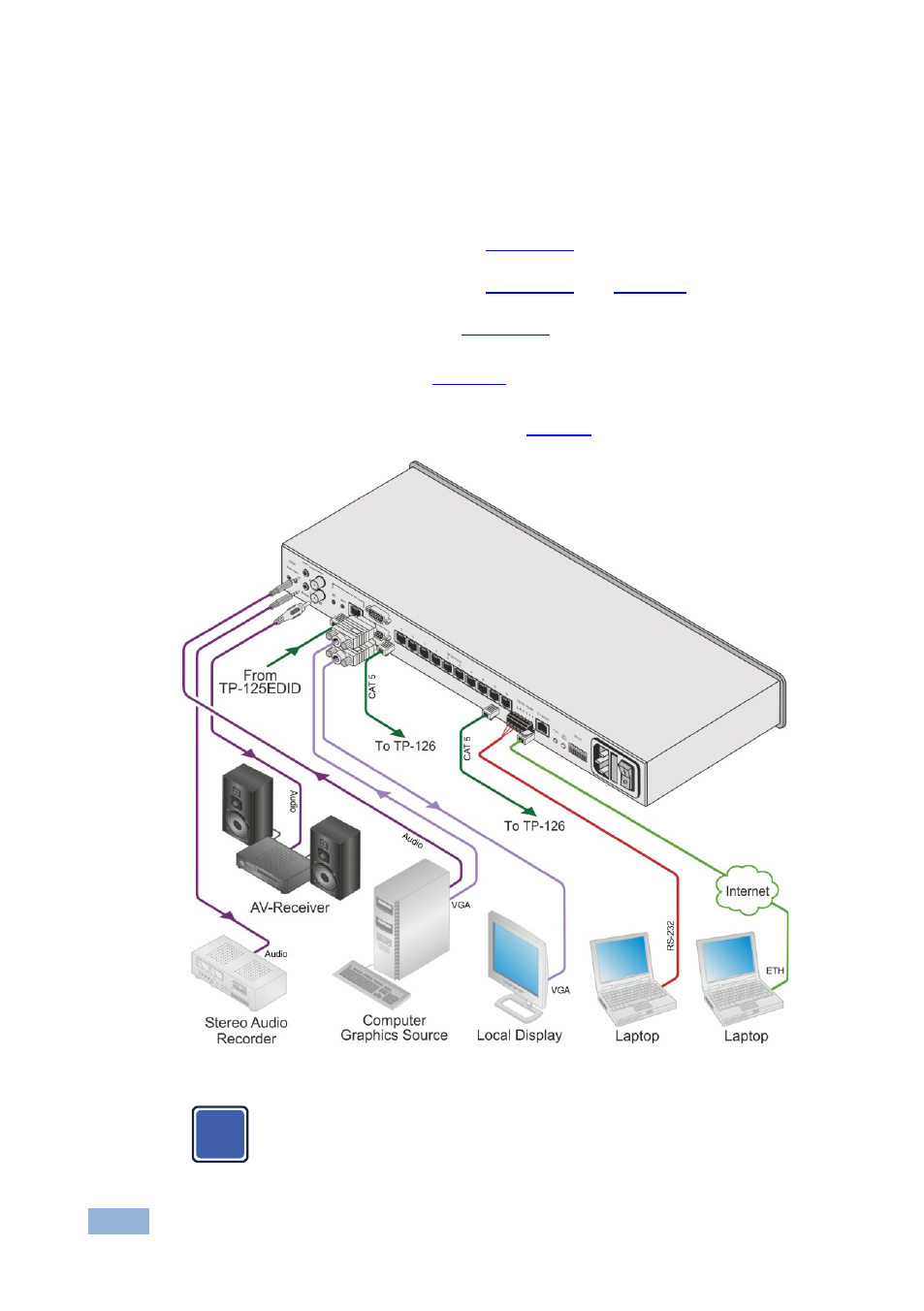
6. Connect the 10 TP OUTPUT STP/UTP connectors to up to 10 TP receivers
(for example, the TP-126 or additional TP-410 units).
7. If required, you can connect a PC and/or controller to the:
RS-232 terminal block (see
Section 5.2
RS-485 terminal block (see
Section 5.3
Section 6
Ethernet connector (see
)
Section 5.4
8. Set the DIP-switches (see
Section 7
9. Connect the power cord (not shown in
We recommend that you use only the power cord that is supplied with this machine
Figure 3: Connecting the TP-410, UXGA-Audio-RS-232 Line Transmitter / DA
When using the TP as the source, adjust the EQ/LEVEL trimmers
immediately after turning the power ON. It is recommended to perform
this adjustment using the OUT local display.
i
- VM-114H (22 pages)
- VM-114H2C (25 pages)
- VM-114H4C (23 pages)
- VS-81ETH (27 pages)
- VS-81ETH (41 pages)
- VM-9T (13 pages)
- VP-12NHD (15 pages)
- VP-5R (20 pages)
- VP-6A (15 pages)
- PT-5R/T (13 pages)
- TP-102HD (13 pages)
- TP-104HD (33 pages)
- TP-112HD (13 pages)
- TP-114 (13 pages)
- TP-202 (15 pages)
- TP-205A (15 pages)
- TP-210 (14 pages)
- TP-210A (15 pages)
- tp-219hd (16 pages)
- TP-305A (15 pages)
- TP-310A (18 pages)
- VM-1H4C (17 pages)
- VP-200xlT (31 pages)
- VP-300THD (12 pages)
- VPM-2 (42 pages)
- SI-1VGA (2 pages)
- SID-DP (2 pages)
- SID-DVI (2 pages)
- SID-H (2 pages)
- SID-VGA (2 pages)
- SID-X1 (2 pages)
- SID-X1 (23 pages)
- SID-X1N (23 pages)
- SID-X2N (31 pages)
- SID-X3N (22 pages)
- 622R (17 pages)
- VS-169TP (7 pages)
- VS-169TP (45 pages)
- WSI-1VGA (2 pages)
- TP-107AV (32 pages)
- RC-62 (94 pages)
- RC-5B2 (137 pages)
- WP-500 (2 pages)
- SV-552 (22 pages)