5pin assignments – RMS Technologies IMD23 W/ POLE DAMPING TECHNOLOGY User Manual
Page 8
RMS Technologies
Page 8
Version 1.10
IMD23/23DE Manual
12/3/2007
5
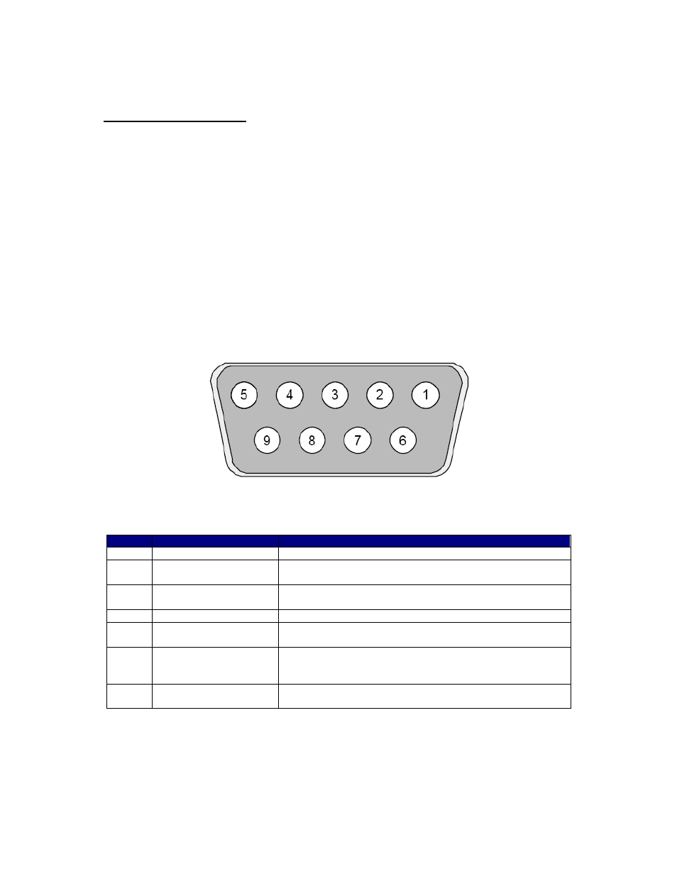
PIN ASSIGNMENTS
A female DB-9 connector cable receives power and provides the control connections for the
IMD23 unit. Active signals are optically isolated. An open collector drive is required to
provide pulses for Step, levels for Direction, and Disable/Enable.
All of these signals are optically isolated. Open-collector drives are required to provide
pulses for Step, levels for Direction, and Disable. The common +ve supply can be +ve 5 to
30 VDC with respect to the signal input; however if the supply is greater than 5 VDC then a
resistor must be inserted in series with each signal line to limit the current to 10 mA.
As you may have noticed, Pins 1 & 6 are connected to power positive and Pins 2 & 7 are
connected to the negative. It is recommended that both sets of pins be used to connect to
the power supply.
View on Face of Mating Socket
Pin
Function
Description
1 & 6
PWR +ve
Motor Supply Voltage. +12 to 48 VDC
2 & 7
PWR –ve
The ground or return of the power supply connects
here
3
+5VDC Out
Used to power the optos (unit will not be opto-isolated
if using this 5V to supply the opto with power)
4
Step
Connects to the open collector drive.
5
Disable
This input is used to enable/disable the output of the
driver
8
Opto Supply
+5 VDC input used to supply power to the isolated
logic inputs. A resistor must be used on all inputs if
the supply is greater than 5 VDC*
9
Direction
This input is used to change the rotation direction of
the motor
Pin Assignments
*Place resistors on all inputs: step (pin 4), direction (pin 9) and disable (pin 5) if your
supply is greater than 5VDC in order to limit the current to 10mAmps. It is the customer’s
preference to either optically isolate the inputs (using a separate supply) or to jumper pins
3 & 8 for ease of use. No harm will be done by connecting the unit in either way.