Pin assignments – RMS Technologies R101 DRIVER/INDEXER User Manual
Page 8
RMS Technologies
Page 8
Version 1.31
R101 Single Axis Driver/Indexer Manual
10/1/2007
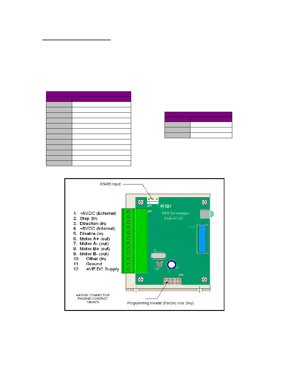
5. PIN ASSIGNMENTS
A 12 pin pluggable terminal strip connector JP1 provides power and the step and
direction control functions for the module. All of these signals are optically isolated.
Open-collector drives are required to provide pulses for Step, levels for Direction
Disable, and Zero Set. The common +ve supply can be +ve 5 to 30 VDC with respect
to the signal input; however if the supply is greater than 5 VDC then a resistor must
be inserted in series with each signal line to limit the current to 10 mA.
JP1 Configuration
Pin No
Function
1
Common +ve External
2
Step (in)
3
Direction (in)
4
+5 VDC Internal
5
Disable (in)
6
Motor A+ (out)
7
Motor A- (out)
8
Motor B+ (out)
9
Motor B- (out)
10
Zero Set (in)
11
Power Ground
12
Power Positive
A separate three pin connector JP3 is provided
for the RS485 bus interface
JP3 Configuration
Pin No
Function
1
A Input (-ve)
2
Ground
3
B Input (+ve)
Figure 2: R101 Pin Usage Diagram