Installation, Figure 2b: typical vertical installation – Comfort-Aire HKV300A User Manual
Page 9
Installation, Operation & Maintenance
HKV SERIES
Heat Controller, LLC
8
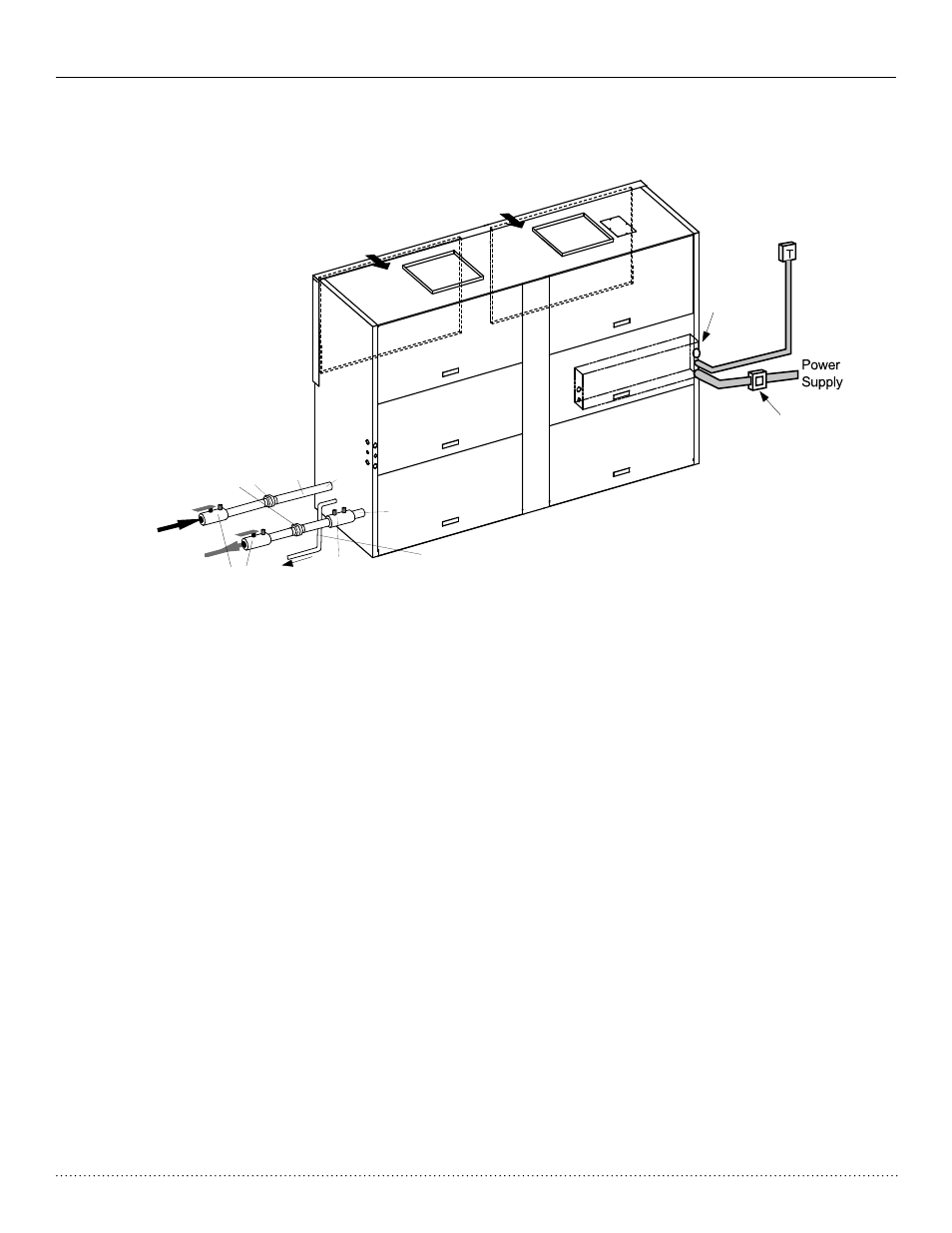
Vertical Location and Access
HKV units are not designed for outdoor installation. Locate the
unit in an indoor area that allows enough space for installation
and for service personnel to perform typical maintenance or
UHSDLUV+.9XQLWVDUHW\SLFDOO\LQVWDOOHGLQDÀRRUOHYHOFORVHWRU
in a small mechanical room. Refer to Figure 2b for an illustration
of a typical installation. Install units with adequate clearance
to allow maintenance and servicing. Conform to the following
guidelines when selecting
unit location:
3URYLGHDGHTXDWHFOHDUDQFHIRU¿OWHUUHSODFHPHQWDQG
GUDLQSDQFOHDQLQJ'2127EORFN¿OWHUDFFHVVZLWK
piping, conduit or other materials. Refer to submittal
drawing for Vertical Unit Dimensions.
2. Provide access for fan and fan motor maintenance and for
servicing of the compressor and coils without removal of
the unit.
3. Provide an unobstructed path to the unit within the closet
or mechanical room to enable removal of the unit if
necessary.
3URYLGHDFFHVVWRZDWHUYDOYHVDQG¿WWLQJVDQG
screwdriver access to the unit side panels, discharge
collar and all electrical connections
Figure 2b: Typical Vertical Installation
Duct System Design & Installation Guidelines
The following application guidelines must be used when
installing HKV units. Failure to follow these guidelines could
result in unsatisfactory unit performance and/or premature
failure of some unit components. Heat Controller, Inc., will not
warrant, or accept responsibility for products which fail, have
GHIHFWVGDPDJHRULQVXI¿FLHQWSHUIRUPDQFHDVDUHVXOWRI
improper application.
7KHGXFWV\VWHPPXVWEHVL]HGWRKDQGOHWKHDLUÀRZ
quietly and must not exceed the maximum allowable
External Static Pressure. To maximize sound attenuation
metal supply and return ducts should include internal
LQVXODWLRQRUEHRIGXFWERDUGFRQVWUXFWLRQIRUWKH¿UVW
IHHWRUHQGRI¿UVWIXOOVL]HGHOERZ
,QVWDOODÀH[LEOHFRQQHFWRULQDOOVXSSO\DQGUHWXUQ
air ducts close to the unit to inhibit sound transfer to the
ducts.
'RQRWLQVWDOOXQLQVXODWHGGXFWLQDQXQFRQGLWLRQHGVSDFH
The unit performance will be adversely affected and
damage from condensate can occur.
2QXQLWVZLWKPXOWLSOHIDQRXWOHWVD³SDLURISDQWV´GXFW
connection must be used for proper air balance and
distribution and to prevent fan oscillation.
Installation
&RQWURO%R[
6XSSO\
$LU
6XSSO\
$LU
Rear Return/Top Discharge shown
Refer to Dimensional Data pages for
other arrangements & dimensions
Ductwork not shown.
All components external
of unit are field supplied.
5HWXUQ$LU
5HWXUQ$LU
24 V Remote
Thermostat
Disconnect Box
Per NEC and
Local Codes
Plug water
in and out
connections
:DWHU
,Q
2SWLRQDO
%DODQFLQJ
9DOYH
5HWXUQ
:DWHU
6XSSO\
:DWHU
6KXWRII
8QLRQV
+RVHV
2SWLRQDO
7R
'UDLQ
:DWHU
2XW
&RQGHQVDWH,QWHUQDOO\
7UDSSHG'RQRWWUDSH[WHUQDOO\
3LWFKKRUL]RQWDOUXQV µSHUIRRW