Hkv series, Installation, operation & maintenance, Heat controller, llc – Comfort-Aire HKV300A User Manual
Page 7
Installation, Operation & Maintenance
HKV SERIES
Heat Controller, LLC
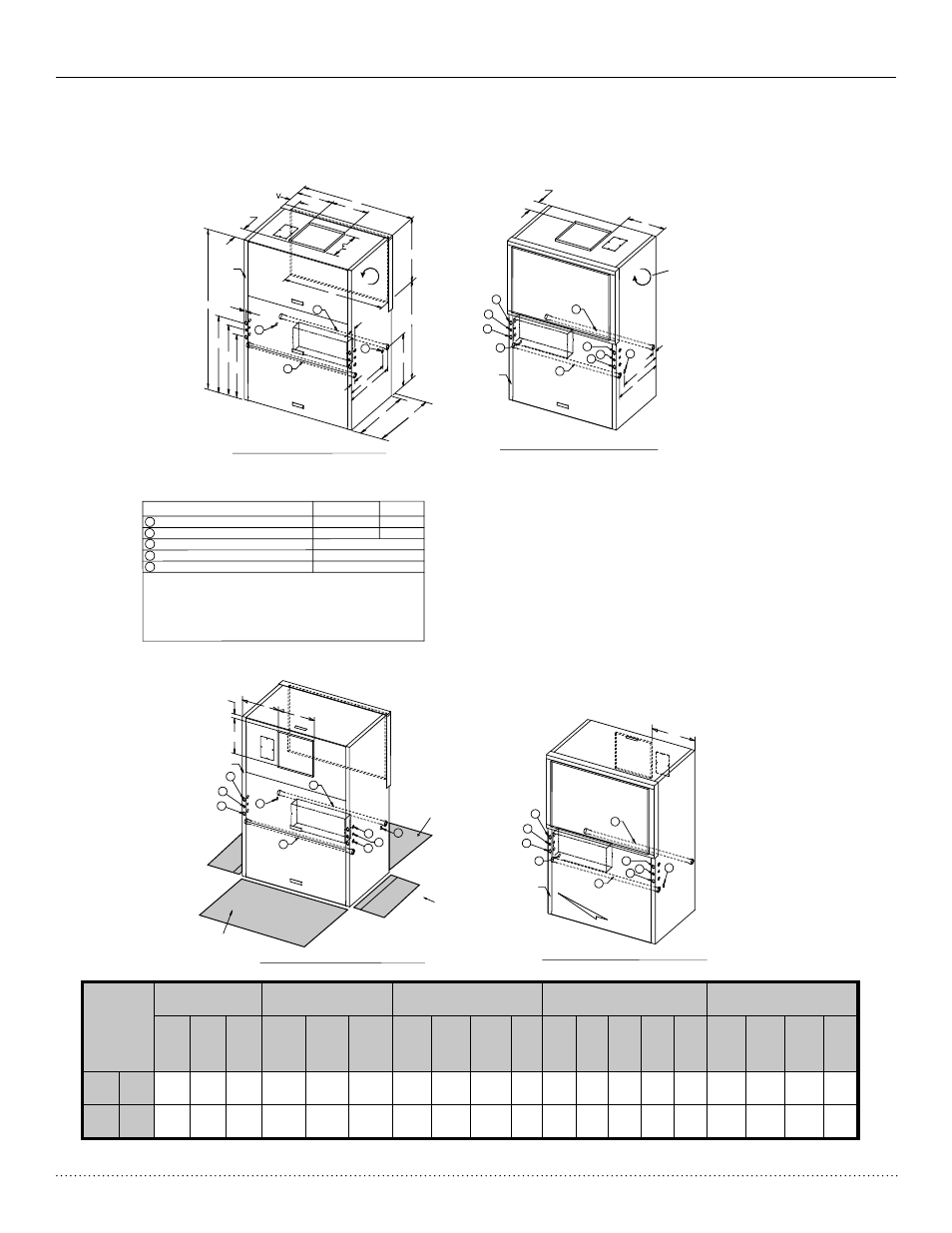
HKV084-150 Dimensional Data
AIR OUT
AIR OUT
AIR OUT
AIR OUT
NRP
BLOWER
ROTATION
NRP
NRP
NRP
NRP
NRP
NRP
NRP
Control Box
Control Box
Control Box
Control Box
NRP
CAP+MSP
RETURN AIR
RETURN AIR
RETURN AIR
RETURN AIR
UPA
BSP
BSP
CSP
CSP
BSP
N
2
2
2
2
3
3
3
3
3
3
4
4
5
5
4
4
3
4
4
5
3
4
4
5
CAP+MSP
CSP+CAP+MSP
1
1
1
1
01
02
C
P
CSP+CAP+MSP
A
NOTE 5
Q
R
S
7.6
B
D
F
T
U
L
K
M
4
4
5
4
4
5
7.6
F
L
K
M
SIDE
SERVICE ACCESS
(See Notes 7 and 9)
SERVICE ACCESS
3’ (91 CM)
FRONT AND BACK
1.7
E
F
D
F
LEGEND
TLV084-120
TLV150
Water Inlet (See Note 2)
Water Outlet (See Note 2)
Condensate Drain (See Note 3)
High Voltage Access (See Note 4)
Low Voltage Access (See Note 4)
1-1/2” FPT
1-1/2” FPT
2” FPT
2” FPT
1” FPT
1-3/8” [3.49 CM]
7/8” [2.2 CM]
BSP - Blower Service Panel
CAP - Control Access Panel
CSP - Compressor Access Panel
MSP - Motor Service Panel
NRP - Non Removable Panel
UPA - Upper Pulley Access
1
2
3
4
5
FRONT RETURN REAR DISCHARGE (FR/RD)
REAR RETURN FRONT DISCHARGE (RR/FD)
REAR RETURN TOP DISCHARGE (RR/TD)
FRONT RETURN TOP DISCHARGE (FR/TD)
NOTES:
1. All dimensions in inches (cm)
2. Water inlet and water outlet connections are available on either side (left or right) of the
unit. Installer must plug water inlet/outlet not being connected to.
3. Condensate drain is available on either side (left or right) of unit. Drain hose and drain
connection will be tied inside the unit. Installer will untie the drain hose, form trap, and
connect to the condensate drain hole of installer’s choice.
4. Electrical access is available on either side (left or right) of unit and is also available in the
front on the left or right side of the unit.
5. Overall Depth - Add 3.12”(8 cm) for 1”(2.5 cm) or 2”(5 cm) Filter Rack; 5.12” for 4” filter
rack and for FD, RD additional 1.06”(2.7cm) for supply air duct flange.
6. Overall cabinet height dimension does not include duct flange when in top discharge
configuration.
7. While access to all removable panels may not be required, installer should take care to
comply with all building codes and allow adequate clearance for future field service.
8. Units require 3 feet(91 cm) clearance for water connections, CAP, CSP, MSP and BSP
service access.
9. Side service access must be 2 feet(9.4 cm) on any side that connections are made. If no
connections are made on a side then service access can be 6 inches(1.5 cm) minimum.
10. Filter removal is from bottom of frame, allow 2 feet(9.4 cm) access for servicing.
BSP
BSP
UPA
ALL CONFIGURATIONS REQUIRE SERVICE ACCESS AREA
DESCRIBED IN NOTES 7, 8, 9, AND 10.
(See Notes 7 and 8)
(See Notes 7 and 10)
Model
Overall Cabinet
Discharge Connections
Duct Flange
Water Connections
Electrical Knockouts
Return Air Connections
Using Return Air Opening
A
Depth
Note 5
B
Width
C
Height
D
Supply
Width
E
Supply
Depth
F
K
1
Water
Inlet
L
2
Water
Outlet
M
3
Con-
densate
N
O1
O2
P
Q
R
S
Return
Depth
T
Return
Height
U
V
084
-120
in.
cm.
34.0
86.4
53.1
134.9
79.0
200.7
17.5
44.5
17.6
44.6
17.8
45.1
31.0
78.7
3.0
7.6
27.0
68.6
25.6
65.1
31.0
78.7
38.0
96.4
34.6
87.7
1.0
2.5
3.0
7.6
48.0
121.9
32.4
82.2
44.6
113.3
2.7
6.9
150
in.
cm.
34.0
86.4
53.1
134.9
79.0
200.7
21.4
54.4
17.6
44.6
17.8
45.1
31.0
78.7
3.0
7.6
27.0
68.6
25.6
65.1
31.0
78.7
38.0
96.4
34.6
87.7
1.0
2.5
3.0
7.6
48.0
121.9
32.4
82.2
44.6
113.3
2.7
6.9
6