Caution, Electrical - low voltage – Comfort-Aire HKV300A User Manual
Page 19
Installation, Operation & Maintenance
HKV SERIES
Heat Controller, LLC
18
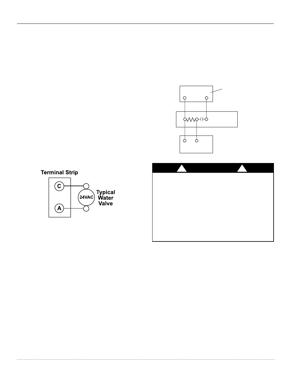
&
&
7KHUPRVWDW
<
<
$90
7DFR9DOYH
+HDWHU 6ZLWFK
Low Water Temperature Cutout - FP1
7KH&;0FRQWURODOORZVWKH¿HOGVHOHFWLRQRIVRXUFHÀXLGORZ
temperature cutout points. The factory setting of FP1 is set for
water (30°F [-1.1°C]). In cold temperature applications jumper
JW3 (FP1- antifreeze 10°F [-12.2°C]) should be clipped as
shown in Figure 10 to change the setting to 10°F [-12.2°C], a
more suitable temperature when using antifreezes. It should
EHQRWHGWKDWWKHH[WHQGHGUDQJHRSWLRQVKRXOGEHVSHFL¿HGWR
operate the HKV Series at entering water temperatures below
60°F [15°C].
Accessory Connections
A terminal paralleling the compressor contactor coil has been
provided on the CXM control of the HKV line. "A" has been pro-
vided to control accessory devices, such as water valves, elec-
WURQLFDLUFOHDQHUVKXPLGL¿HUVHWF1RWH7KLVWHUPLQDOVKRXOG
be used only with 24 Volt signals and not line voltage signals.
This signal operates with the compressor contactor. See Figure
11 or the wiring schematic for details.
Water Solenoid Valves
When using external solenoid valves on ground water installa-
tions, a slow closing valve may be desired. Figure 11 illustrates
a typical slow closing water control valve wiring which will limit
wasted water during a lockout condition. A slow closing valve
may be required to prevent water hammer. When using an AVM
-Taco Slow Closing valve on HKV Series equipment Figure 12
wiring should be utilized. The valve takes approximately 60 sec-
RQGVWRRSHQYHU\OLWWOHZDWHUZLOOÀRZEHIRUHVHFRQGVDQG
it activates the compressor only after the valve is completely
opened (by closing its end switch). Only relay or triac based
electronic thermostats should be used with the AVM valve.
When wired as shown, the valve will operate properly with the
following notations:
1-The valve will remain open during a unit lockout.
Figure 11: Accessory Wiring
Figure 12: Well Water AVM Valve Wiring
CXM
TL Unit
Electrical - Low Voltage
2-The valve will draw approximately 25-35 VA through the “Y”
signal of the thermostat. Note: This can overheat the anticipa-
tors of electromechanical thermostats. Therefore only relay or
triac based thermostats should be used.
CAUTION! 0DQ\XQLWVDUHLQVWDOOHGZLWKDIDFWRU\RU¿HOG
supplied manual or electric shut-off valve. DAMAGE WILL
OCCUR if shut-off valve is closed during unit operation. A
high pressure switch must be installed on the heat pump
VLGHRIDQ\¿HOGSURYLGHGVKXWRIIYDOYHVDQGFRQQHFWHGWR
the heat pump controls in series with the built-in refrigerant
circuit high pressure switch to disable compressor operation
LIZDWHUSUHVVXUHH[FHHGVSUHVVXUHVZLWFKVHWWLQJ7KH¿HOG
installed high pressure switch shall have a cut-out pressure
of 300 psig and a cut-in pressure of 250 psig. This pressure
switch can be ordered from Heat Controller with a 1/4” inter-
QDOÀDUHFRQQHFWLRQDVSDUWQXPEHU%1
CAUTION!
!
!