Warning, Caution, Unit start up procedure – Comfort-Aire HKV300A User Manual
Page 44
Installation, Operation & Maintenance
HKV SERIES
Heat Controller, LLC
43
1. Turn thermostat fan position to “ON”. Blower should start.
%DODQFHDLUÀRZDWUHJLVWHUV
3. Adjust all valves to their full open position. Turn on the line
power to all heat pump units.
4. Operate unit in cooling cycle. Room temperature should
be approximately 45-100°F [7-38°C] DB. For Start-up
check, loop water temperature entering the heat pumps
should be between 45°F [7°C] and 110°F [43°C].
5. Two factors determine the operating limits of a Heat
Controller HKV System– (a) return air temperature, and
(b) water temperature. When any one of these factors is at
a minimum or maximum level, the other factor must be at
normal levels to ensure proper unit operation.
a. Adjust the unit thermostat to the warmest position.
Slowly reduce thermostat setting until the
compressor activates.
b. Check for cool air delivery at the unit grille within a
few minutes after the unit has begun to operate.
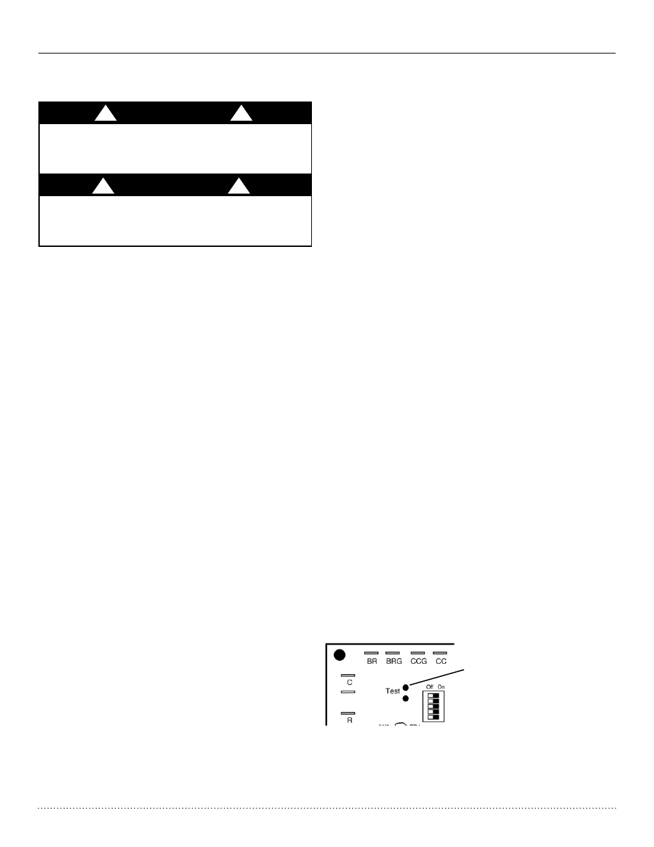
Note8QLWVKDYHD¿YHPLQXWHWLPHGHOD\LQWKHFRQWUROFLUFXLW
that can be eliminated on the CXM PCB as shown below in
Figure 14. See controls description for detailed features of the
control.
c. Verify that the compressor is on and that the water
ÀRZUDWHLVFRUUHFWE\PHDVXULQJSUHVVXUHGURS
through the heat exchanger using the Pete’s
plugs and comparing to Table 7.
d. Check the elevation and cleanliness of the conden-
sate lines. Dripping may be a sign of a blocked line.
Check that the condensate trap includes a water
seal.
e. Refer to Table 9. Check the temperature of both
supply and discharge water. If temperature is within
range, proceed with test. If temperature is outside
operating range, check cooling refrigerant pressures
LQ7DEOH9HULI\FRUUHFWZDWHUÀRZE\FRPSDULQJ
unit pressure drop across the heat exchanger versus
the data in Table 9. Heat of rejection can be calcu-
ODWHGDQGFRPSDUHGWRVSHFL¿FDWLRQFDWDORJ
f. Check air temperature drop across the coil when
compressor is operating. Air temperature should
drop between 15°F [8°C] and 25°F [14°C].
g. Turn thermostat to “OFF” position. A hissing noise
indicates proper functioning of the reversing valve.
6. Operate the heat pump in the heating cycle imme-
diately after checking cooling cycle operation. Allow
¿YHPLQXWHVEHWZHHQWHVWVIRUSUHVVXUHWRHTXDO-
ize or cycle the reversing valve to equalize.
a. Turn thermostat to lowest setting and set thermostat
switch to “HEAT” position.
b. Slowly turn thermostat to a higher temperature until
the compressor activates.
c. Check for warm air delivery at the unit grille within a
few minutes after the unit has begun to operate.
d. Check the temperature of both supply and discharge
water. Refer to Table 8. If temperature is within
range, proceed with test. If temperature is outside
operating range, check heating refrigerant pressures
in Table 8.
e. Check air temperature rise across the coil when
compressor is operating. Air temperature should
rise between 20°F [11°C] and 30°F [17°C]. Heat of
extraction can be calculated and compared to speci-
¿FDWLRQFDWDORJ
f. Check for vibration, noise, and water leaks.
7. If unit fails to operate, perform troubleshooting analysis
(CXM manual). If the check described fails to reveal the
problem and the unit still does not operate, contact a
trained service technician to ensure proper diagnosis and
repair of the equipment.
8. When testing is complete, set system to maintain desired
comfort level.
9. BE CERTAIN TO FILL OUT AND FORWARD
ALL WARRANTY REGISTRATION CARDS
TO HEAT CONTROLLER.
Note: If performance during any mode appears abnormal,
refer to the troubleshooting section of CXM manual. To obtain
maximum performance the air coil should be cleaned before
VWDUWXS$VROXWLRQRIGLVKZDVKHUGHWHUJHQWDQGZDWHULV
recommended.
Short test pins together to
enter Test Mode and speed-
up timing and delays for 20
minutes.
Figure 14: Test Mode Pins
CXM Board
Unit Start Up Procedure
WARNING! When the disconnect switch is closed, high
voltage is present in some areas of the electrical panel.
Exercise caution when working with energized equipment.
INSTALLER CAUTION! After making water connections on
units equipped with ClimaDry, ensure the three union nuts
on the internal three-way water valve are tight.
WARNING!
!
!
CAUTION!
!
!