Goulds Pumps AF (Axial Flow) (42"/1200mm/54/60"/66") LM/LMR Bearings - IOM" User Manual
Page 33
AF (42-66) IOM
33
below 200
°F., which will be the normal temperature for
the installation.
temperature, without any change in speed or loading
can mean a lubrication difficulty or the approach of
bearing failure.
INSTALLING A BEARING
Long bearing life is dependent on careful handling of
the bearing when it is out of the housing and during the
installation procedure. Dirt and rough handling are
prime enemies of precision bearings. Bearings should
be pressed, not “hammered” into place. If heat is used
to facilitate the installation, a hot oil bath is the best
method.
THRUST BEARING ORIENTATION
Fig. 20 at the end of this section shows the axial thrust
bearing (112C) in the outboard location. This is used
for top suction pumps.
End suction pumps have the flow and axial thrust in
the opposite direction. Therefore, the complete thrust
bearing assembly is reoriented in the opposite
direction. This does not change the basic disassembly
procedure, other than the sequence of installing the
thrust bearing assembly components on the shaft.
The illustration shows the thrust bearing (112C)
mounted on a sleeve (196). For the other bearing
orientation, the bearing is mounted on an extension of
the spacer (443), eliminating the separate sleeve.
SHAFT SEALING
A packed stuffing box or mechanical seal is used to
seal the AF pump shaft. Both methods are described
below.
PACKED STUFFING BOX
The original equipment packing is a suitable grade for
the service intended. To pack the standard stuffing
box use the following procedure: For the special (6)
ring packing arrangement see the appendix 1.
1. Stuffing box and shaft sleeve must be clean and
free of grit.
2. Form packing over shaft or mandrel of same
diameter. Carefully cut to packing length. Discard
rings cut too short.
3. Pre-form each ring by coiling 1 -1 /2 turns.
4. To install packing rings, do not pull straight.
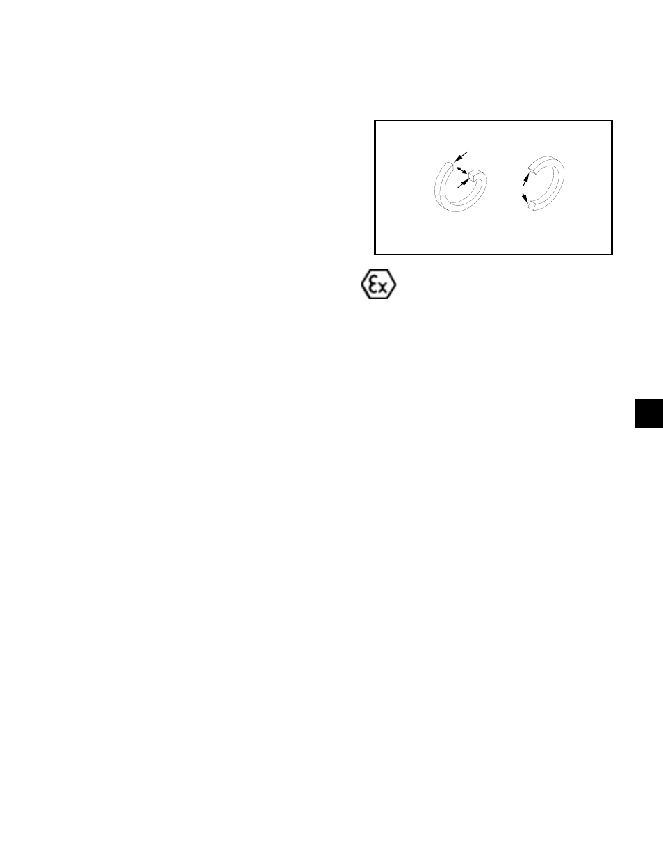
Expand the coil as a coil spring, see Fig 17 for the
correct and incorrect method of installing packing.
Expand the first coil as shown and insert into stuffing
box. Tamp packing to stuffing box shoulder firmly with
the gland. Note, where the cut is positioned.
5. Install the first lantern ring into the stuffing box.
Failure to property locate the lantern ring with the
flush port will result in insufficient packing
lubrication.
6. Install the second and third coil as required by
sectional drawing, staggering the cut 90
° to 120°.
7. Install the second lantern ring into stuffing box,
carefully noting its proper position on the sectional
drawing.
8. Install the third and fourth coil as required by
sectional drawing, staggering the cut 90
° to 120°.
9. After packing and lantern rings are properly
installed, insert gland into stuffing box. Tighten
gland nuts finger tight only. The shaft should turn
freely.
10. Turn lubricant supply on, start pump, and adjust
the gland as described in Section III-E Stuffing Box
Adjustment.
11. Periodic maintenance is absolutely required for all
packed pumps. Normal shaft run-out should be
under .005” to avoid pounding of stuffing box
packing. With excessive shaft run-out, shaft
straightening or replacement is necessary.
Packed stuffing boxes are not allowed in an
ATEX classified environment.
PACKING RINGS
CORRECT
INCORRECT
Fig. 17
4