Warning – Goulds Pumps AF (Axial Flow) (42"/1200mm/54/60"/66") LM/LMR Bearings - IOM" User Manual
Page 23
AF (42-66) IOM
23
1. Check Belt Fit - Regardless of the belt section
used, the belt should never be allowed to bottom
in the groove. This will cause the belts to lose
their wedging action and slippage can occur.
Sheaves or belts that permit such a condition to
occur should be changed.
2. Maintain Proper Belt Tension - Proper tension
is essential for long belt life. Improper tension
could cause belt fatigue and/or hot bearings.
3. Impeller Alignment after Belt Tensioning – If
the impeller was aligned prior to belt tensioning a
check should be made to determine that it is still
centered. An off center impeller may rub and
cause unnecessary pump damage. Belt Tension
will usually cause impeller misalignment opposite
the motor. Be sure to align or re-align in
accordance with the Impeller Alignment section
page 26.
The general method of tensioning belts is given
below, and should satisfy most drive requirements.
General Method:
STEP 1. Reduce the center distance so that the belts
may be placed over the sheaves and in the grooves
without forcing them over the sides of the grooves.
Arrange the belts so that both belt spans have a
proximately the same sag between the sheaves.
Apply tension to the belts by increasing the center
distance until the belts are snug, see Fig. 13.
WARNING
Do not operate the pump without the proper drive
guard in place. Failure to observe this warning
could result in personal injury to operating
personnel
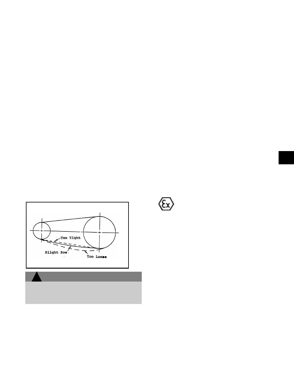
STEP 2. Operate the drive a few minutes to seat the
belts in the sheave grooves. Observe the operation of
the drive under its highest load condition (usually
starting). A Slight bowing of the slack side of the drive
indicates proper tension. If the slack side remains
taut during the peak load, the drive is too tight.
Excessive bowing or slippage indicates insufficient
tension. If the belts squeal as the motor begins
operation or at some subsequent peak load, they are
not tight enough to deliver the torque demanded by the
drive machine. The drive should be stopped and the
belts tightened.
STEP 3. Check the tension on a new drive frequently
during the first day by observing the slack side span.
After a few days of operation the belts will seat
themselves in the sheave grooves and it may become
necessary to readjust so that the drive again shows a
slight bow in the slack side.
Other methods of determining proper belt tension can
be obtained from the drive manufacturer.
5. Use Belt Guards - Belt guards protect personnel
from danger and the drive from contamination.
Inspect periodically to assure that belts do not rub
against guard.
6. Keep Belts Clean - Dirt and grease reduce belt life.
An occasional wiping with a dry cloth to remove any
build-up of a foreign material can extend the life of
the belt. Should oil or grease splatter onto the
belts, clean with soap and water.
Belt dressing affects performance only temporarily and
is never recommended. Maintaining a clean drive is a
better practice.
If any questions arise pertaining to the drive limitations,
consult the manufacturer.
GEAR DRIVE (COUPLINGS)
The coupling used in an ATEX classified
environment must be properly certified.
Remove the guard or guards by referring to the
assembly/disassembly instructions. Disconnect
motor/gearbox and the pump/gearbox coupling halves
before proceeding with the alignment. First, align the
pump/gearbox coupling then the motor/gearbox
coupling. Check both coupling connections for parallel
and angular alignment by either the Dial Indicator or
Straight-Edge Method outlined below.
Good alignment is achieved when the dial indicator
readings, for both parallel and angular misalignment,
are .003" (.076mm) Total Indicated Reading (T.I.R.) or
less when the pump and driver are at operating
temperature (Final Alignment). Fig. 14 describes what
to look for.
Fig. 13
!
3