Pipe hung installation – Goulds Pumps AF (Axial Flow) (42"/1200mm/54/60"/66") LM/LMR Bearings - IOM" User Manual
Page 21
AF (42-66) IOM
21
PIPE HUNG INSTALLATION
LOCATION OF UNIT
The pump should be located in a clean, dry area free
from flooding. The area should provide adequate
space for maintenance and repair, considering
complete disassembly and handling of equipment.
The unit should be positioned to provide the most
efficient pipeline system.
PIPING
Short, direct suction and discharge pipelines having a
minimum of elbows and fittings will result in the least
amount of pipe friction. Excessive friction losses will
result in insufficient capacity and cavitation. Future
access to the pump impeller and shaft will require
removal of a section of discharge pipe (spool piece).
NOTE: The horizontal pipe flange must be parallel
with the pump flange before the bolts are
tightened. If the flanges are not parallel, forcing
them parallel by tightening the bolts may put
excessive strain on the pump.
INSTALLATION OF PUMP IN PIPELINE
1. Connect the pump top flange to the vertical
pipe and tighten flange bolts. Level pump
within .005” (0.42 mm)/Meter.
2. Check the impeller clearance in the casing so
that it is reasonably well centered using the
criteria that the minimum gap at the vane.
3. O.D. is at least 50% of the maximum gap (see
the impeller alignment worksheet, pg. 28 for
instructions)
4. Connect the casing flange to the spool piece
and tighten the flange bolts.
INSTALLATION OF THE DRIVER
Install the driver (motor and reduction gear on a
separate sub-base) as indicated on the installation
drawing for the pump. The universal joint drive shaft
requires the gear and pump shafts be parallel within 1
degree but off-set as indicated on the drawing. The
optimal universal joint life is obtained with off-set shaft
angles of 1 to 3 degrees.
Level the driver base relative to the pump, in
accordance with the proceeding paragraph using
leveling wedges adjacent to the anchor bolts. Partially
tighten the anchor bolt nuts and check the shaft
alignment between the motor and reduction gear. If the
alignment is reasonably satisfactory, grout the base in
place.
After the grout has hardened, tighten the anchor bolt
nuts. Check and correct the motor shaft alignment. We
recommend the actual shaft misalignment for the
flexible couplings be considerably less than the
maximum allowed by the coupling manufacturer for
long coupling life and reduced vibration levels.
CONNECTION TO PUMP DRIVER
The pipe hung pump is connected to the driver via a
drive shaft and universal joints at each end. Follow the
drive shaft installation instructions and the angle limits
per the pump installation drawing. An extendable guard
is provided for the drive shaft and should be used any
time the pump driver is rotating.
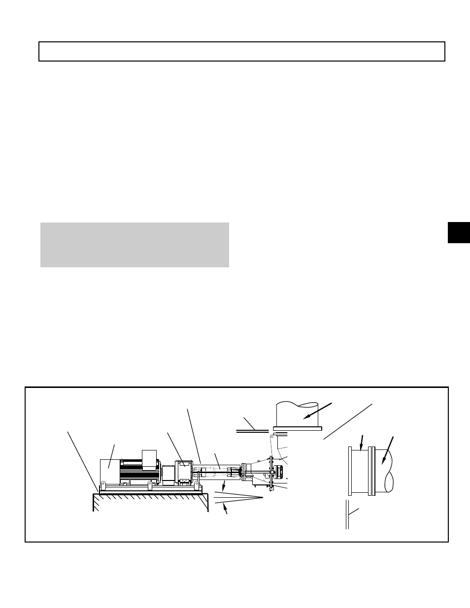
Fig. 11A
Foundation
Horizontal
Pipe
Vertical
Pipe
Spool Piece
Drive
Shaft
Motor
Reduction
Gear
Level Sub-base
Shaft Offset
+/- 1 to 3 deg.
Flanges must
be Parallel
Flanges must
be Parallel
Extendable
Guard
Pump must be
level .005”/ft
3