Goulds Pumps AF (Axial Flow) (42"/1200mm/54/60"/66") LM/LMR Bearings - IOM" User Manual
Page 17
AF (42-66) IOM
17
6. Pour grout through the grout holes in the sub-base,
up to level of dam. Remove air bubbles from grout
as it is poured by puddling, using a vibrator, or
pumping the grout into place. Non-shrink grout is
recommended.
7. Allow grout to set.
8. Fill remainder of sub-base with grout. Remove air
as before (Fig. 7)
9. Allow grout to set at least 48 hours.
10. Tighten foundation bolts.
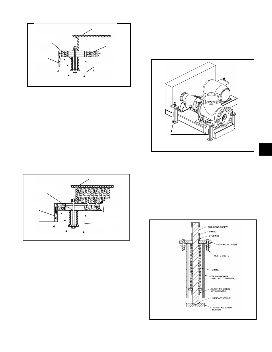
SPRING MOUNTED BASE
Fig. 8 shows a V-belt driven AF pump on a spring
mounted sub-base. Sub-bases supported by spring
pockets assure that the pump remains level,
regardless of vertical movement due to thermal pipe
expansion during operation.
The following is a brief description of the spring pocket
components and their function (see Fig. 9). The
adjusting screw is used to compress or relax the
spring. Turning the screw causes the adjusting screw
nut assembly to move vertically and change the
amount of force the spring exerts against the spring
retainer, which is fastened to the sub-base. The stop
nut is to limit the vertical up motion of the sub-base in
case part of the load is removed from the pump unit
Fig. 10
SPRING
POCKETS
Fig. 8
BOLT
BASEPLATE
GROU
DAM
GROUT
FOUNDATION
Fig. 9
Fig. 6
Fig. 9
BOLT
BASEPLATE
DAM
GROUT
FOUNDATION
Fig. 7
Fig. 8
3