Caution – Goulds Pumps 3408A - IOM User Manual
Page 41
Press the stationary mechanical seal seats into both of the
gland plates. Lightly lubricate the gland plates to ease
assembly. See Figure 17.
IMPORTANT: Steps 11 through 21 must be completed,
on the outboard end, within 10 to 12 minutes to assure
proper placement of the mechanical seals
11. Press new lip seals into the gland plates. Before
installing the lip seals, lubricate the lip seals with
lightweight oil.
NOTE: Lip seals should sit against the machined
shoulder in the gland plates. The lip seals should face
away from the mechanical seal seats. See Figure 18.
12. Lubricate and roll the O-rings into the grooves in each
gland plate.
13. Press the gland plates into the stuffing boxes and
secure using the socket-head capscrews.
NOTE: Because of the compression of the O-ring, it
may be difficult to press the O-ring into the stuffing
box. Use longer socket-head capscrews to start the
gland plate into the stuffing box. To prevent the
mechanical seal spring from pushing the gland plate
back out of the stuffing box, remove one long
socket-head capscrew at a time and replace with a
regular socket-head capscrew.
Figure 24: Pressing Impeller on Shaft
Figure 25: Installing Mechanical Seal Head
Figure 26: Installing Stuffing Box
14
Lubricate and roll the O-rings into the groove in each
stuffing box.
NOTE: At this point reassemble the rotating element
by starting on the outboard end first (the end opposite
the coupling) as this end locates the settings of the
mechanical seal.
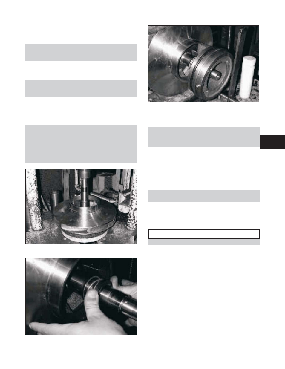
15. Lightly coat the outboard end of the pump shaft with
P-80 Rubber Lubricant Emulsion, vegetable oil, or
equal and slide the mechanical seal head onto the shaft.
See Figure 25.
16. Slide the stuffing box, with the gland plate, fully on
the shaft, being very careful that the head and seat of
the mechanical seal do not get damaged.
NOTE: Compress the seal spring only as far as
required to install the bearings. See Figure 26.
17. Fill lip seal cavity with approximately .50 ounces of
grease.
18. Heat the ball bearings using dry heat to 10% – 15%
soluble oil and water, or an induction heater.
$
!
CAUTION
Do not exceed a temperature of 275°F..
19. Using gloves, slide the heated bearing onto the shaft
against the shaft shoulder. See Figure 19.
20. Install the locknut and lockwasher on the outboard end
of the shaft. Make certain that the locknut is secure and
bend over the tabs on the lockwasher. See Figure 20.
21. Allow the bearing to cool to room temperature. Coat the
exposed sides of the bearing with two or three ounces of
recommended grease. Drive as much grease as possible
into the bearing using a putty knife or similar tool.
22. Remove the grease relief plug; coat the inside of the
bearing housing with grease and then slide the housing
into place over the bearing. Attach the bearing housing
to the stuffing box with the capscrews. Leave the
grease relief plug out of the outboard housing until the
pump is run for a minimum of two hours and the
system has reached its normal operating temperature.
3408A IOM 6/08
33
4