Goulds Pumps 3408A - IOM User Manual
Page 35
REPLACING MECHANICAL SEALS
AND BEARINGS
(without removing the upper half of the casing)
NOTE: In order to replace the mechanical seal and
bearing housing on the coupler end, you must use a
spacer type coupler.
s
!
WARNING
Unexpected Startup Hazard
Disconnect and lockout power before servicing.
Failure to follow these instructions could result in seri-
ous personal injury or death, or property damage.
$
!
CAUTION
Extreme Temperature Hazard
Allow pump temperatures to reach acceptable levels
before proceeding. Open the drain valve. Do not
proceed until liquid stops coming out of the drain
valve. If liquid does not stop flowing from the drain
valve, isolation valves are not sealing and should be
repaired before proceeding. After liquid stops flowing
from drain valve, leave the valve open and continue.
Remove the drain plug located on the bottom of the
pump housing. Do not reinstall the plug or closethe
drain valve until reassembly is completed.
Failure to follow these instructions could result in
moderate personal injury or property damage.
1.
Close valves on suction and discharge sides of pump.
If no valves have been installed, it will be necessary to
drain the system.
2.
Remove the coupler guard. For spacer coupler, loosen
the capscrews which secure the coupler flanges to the
coupler hubs. Remove the coupler flanges and sleeve
by compressing the flanges and pulling out from
beneath the hubs or by loosening the Allen set screws
and sliding the hubs back on the shafts. Remove the
coupler hubs from the pump shaft. For non-spacer
couplers, loosen set screws and slide flanges back on
shafts and remove rubber element.
3.
Remove the capscrews from each of the bearing
housings and remove the bearing housings by placing
two 2.0" long full-threaded capscrews or Allen set
screws in the jackscrew holes provided.
4.
Bend back the lockwasher tab and remove both the
lockwasher and locknut from the outboard end of the
shaft (the opposite side of the coupling).
5.
Remove the socket-head capscrews holding the gland
plates to the stuffing boxes.
6.
Insert threaded rods into the tapped holes in the gland
plate and install a fixture on the threaded rods to use a
puller. See Figure 14 for Dimensions of Universal
Fixture (PN: AC2394). Using the puller, tighten the
bolt in the center of the fixture to remove the bearing
and gland plate from the shaft. See Figures 15 and 16.
$
!
CAUTION
Pump Damage Hazard
Failure to remove the socket-head capscrews before
trying to pull the bearings off could cause damage to
the pump.
Failure to follow these instructions could result in
moderate personal injury or property damage.
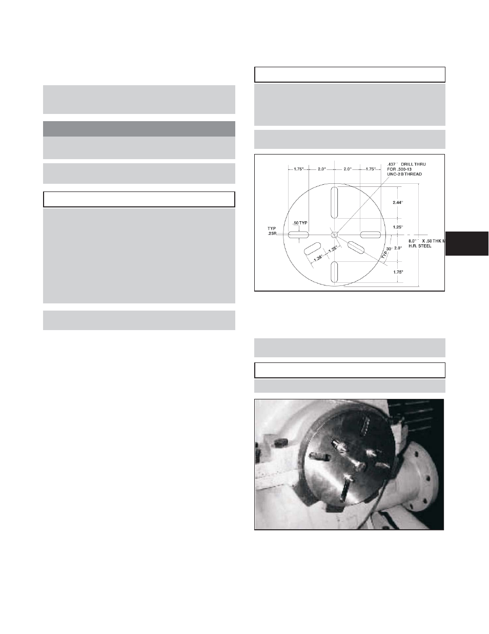
Figure 14: Dimensions for Universal Fixture
(PN: AC2394)
7.
Remove the inboard bearing and gland plate in the
same manner.
NOTE: The locknut and lockwasher are not used on
the inboard bearing.
$
!
CAUTION
Do not reuse the ball bearings
Figure 15: Removing bearing and gland plate
using universal fixture
3408A IOM 6/08
27
4