Caution – Goulds Pumps 3408A - IOM User Manual
Page 37
$
!
CAUTION
Use a flashlight and make sure the mechanical seal
spring is seated properly into the spring holder and
around the bellows of the mechanical seal before
continuing. Without properly seating the spring, the
seal will fail.
5.
Slide the gland plate, over the shaft, being very careful
that the head and the seat of the mechanical seal do not
get damaged. Then press the gland plate with the
O-ring into the stuffing box and tighten the
socket-head capscrews.
NOTE: Because of the compression of the O-ring, it
may be difficult to press the O-ring into the stuffing
box. Use longer socket-head capscrews to start the
gland plate into the stuffing box. Draw-up the bolts
evenly until the gland plate is secure in the stuffing
box. To prevent the mechanical seal spring from
pushing the gland plate back out of the stuffing box,
remove one long socket-head capscrew at a time and
replace with a regular sockethead capscrew.
6.
Heat the ball bearings using dry heat or 10% – 15%
soluble oil and water, or an induction heater.
$
!
CAUTION
Do not exceed a temperature of 275°F
7.
Fill up the lip seal cavity with approximately .50
ounces of grease.
8.
Using gloves, slide the heated bearing onto the shaft
against the shaft shoulder. See Figure 19.
Figure 19: Installing Bearing
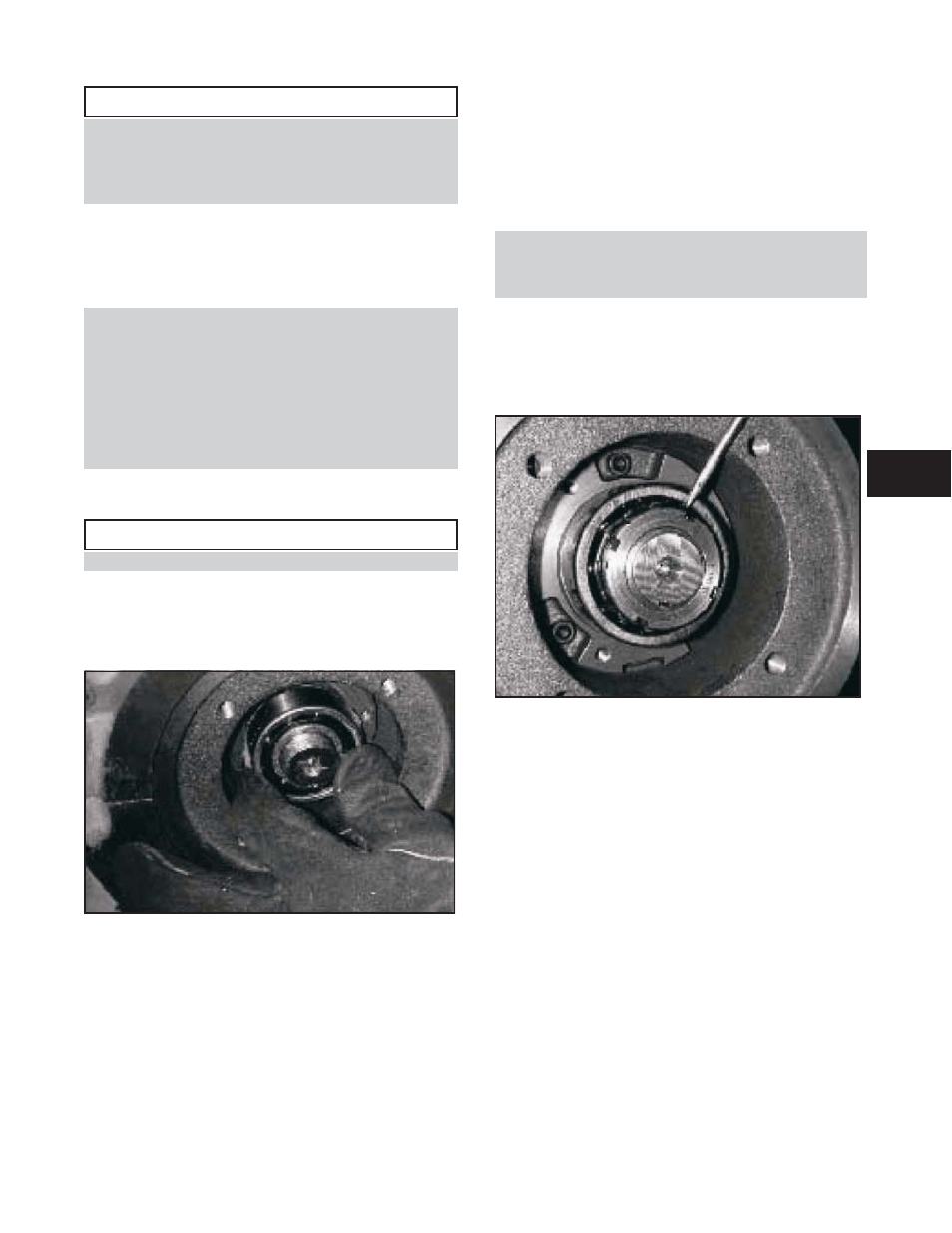
9.
Install the locknut and lockwasher on the outboard end
of the shaft. Make certain that the locknut is secure and
bend over the tabs on the lockwasher. See Figure 20.
10. Allow the bearing to cool to room temperature. Coat
the exposed sides of the bearing with two or three
ounces of recommended grease. Drive as much grease
as possible into the bearing using a putty knife or
similar tool.
11. Remove the grease relief plug; coat the inside of the
bearing housing with grease, and then slide the
housing into place over the bearing. Alternately tighten
the bearing housing capscrews so as not to “cock” the
bearing housing causing bearing to bind. Leave the
grease relief plug out of the outboard housing until the
pump is run for a minimum of two hours and the
system has reached its normal operating temperature.
NOTE: A locknut and lockwasher are not installed on
the inboard end of the pump shaft. It is acceptable to
leave the grease relief plug installed on the inboard
side for Step 11.
12. Repeat steps 1 through 11 for the inboard.
13. Reinstall the coupler, check for alignment, and install
the coupler guard. See the sections entitled Alignment
Procedure and ANSI/OSHA Coupler Guard
Removal/Installation.
Figure 20: Installing Lockwasher and Locknut
3408A IOM 6/08
29
4