Alignment method 1, Alignment method 2 – Goulds Pumps 3408A - IOM User Manual
Page 22
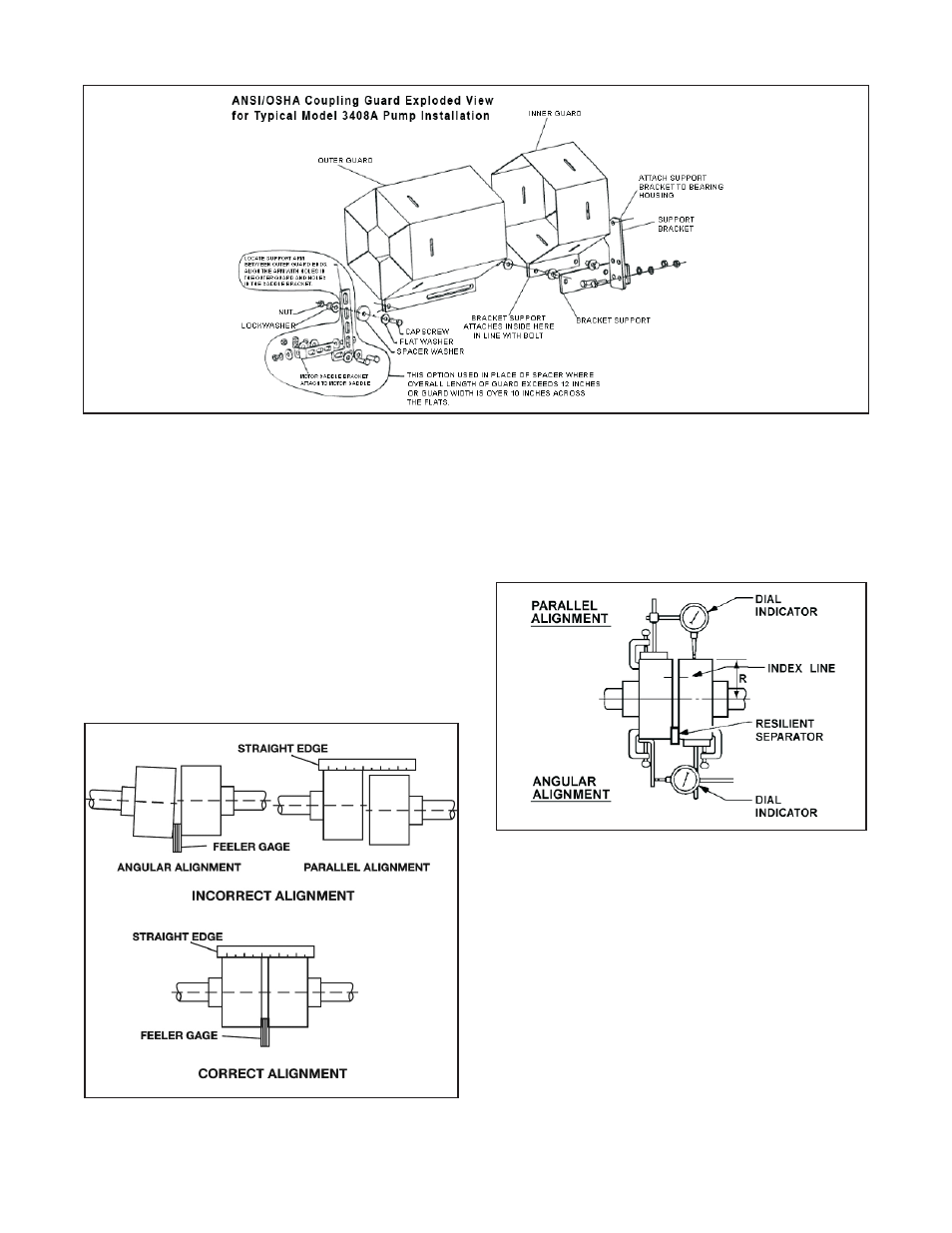
Figure 6: ANSI/OSHA Coupling Guard
Alignment Method 1
Straight Edge Alignment for Standard Sleeve Type Coupler
with Black Rubber Insert
See Figure 7.
Before aligning the coupler, make sure there is at least 1/8
inch end clearance between the sleeve and the two coupler
halves.
1.
Check angular misalignment using a micrometer or
caliper. Measure from the outside of one flange to the
outside of the opposite flange at four points 90° apart.
DO NOT ROTATE COUPLER. Misalignment up to
1/64 inch per inch of coupler radius is permissible.
Figure 7: Checking Alignment (Method 1)
2.
At four points 90° apart (DO NOT ROTATE
COUPLER), measure the parallel coupler
misalignment by laying a straight edge across one
coupler half and measuring the gap between the
straight edge and opposite coupler half. Up to a 1/64
inch gap is permissible.
Figure 8: Checking Alignment (Method 2)
Alignment Method 2
For Orange Hytrel Inserts, 3500 RPM Operation, or All
Other Coupler Types
See Figure 8.
1.
Make sure each hub is secured to its respective shaft
and that all connecting and/or spacing elements are
removed at this time.
2.
The gap between the coupling hubs is set by the
manufacturer before the units are shipped. However,
this dimension should be checked. Refer to the
coupling manufacturer’s specifications supplied with
the unit.
14
3408A IOM 6/08