Ramp to soak function characteristics, Problems with the controller, Alarm functions – NOVUS Controller N480 User Manual
Page 3: Pid auto tune
Controller N480
Novus Produtos Eletrônicos Ltda.
Tel.:+55-51-3323-3600
3/3
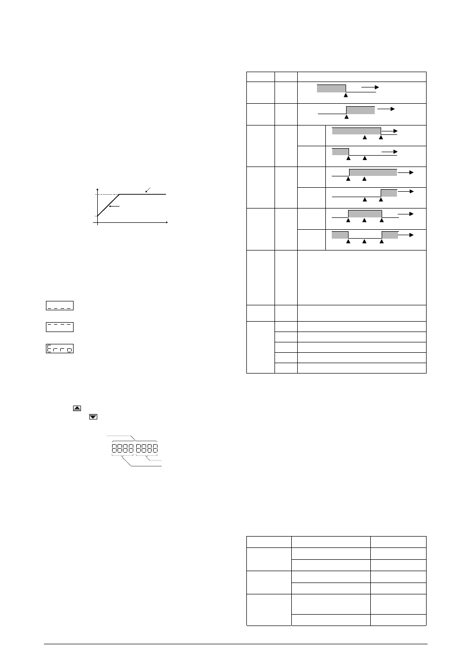
4. RAMP TO SOAK FUNCTION CHARACTERISTICS
This function makes the process temperature rise gradually from the
starting point (present PV) to the temperature value set in “ SP
SP
SP
SP
“
(Ramp). The user defines the rate of rise in degrees per minute at
the “rAtE
rAtE
rAtE
rAtE
” prompt.
When SP is reached the temperature is leveled at this point for 1 to
9999 minutes as programmed at the “ t SP
t SP
t SP
t SP
” prompt. Setting 0
(zero) at “ t SP
t SP
t SP
t SP
” defines an infinite length soak profile.
To disable the ramp function Set 0.0 at the “rAtE
rAtE
rAtE
rAtE
” prompt. To
disable the soak function set 1 at the “ t SP
t SP
t SP
t SP
” prompt (thus making
a 1 minute soak) and the control output will go off in 1 minute. To
restart control set 1 at the “ rvn
rvn
rvn
rvn
” prompt.
After a power failure the controller will resume ramp to soak
execution at the equivalent previous ramp point. If the proces
temperature is the same as the SP (no temperature drop) the
controller will repeat the soak segment.
Soak
Temperature
PV
Ramp
Time
SP
Figure 2 - Ramp to Soak Function
5. PROBLEMS WITH THE CONTROLLER
Connection and configuration errors state for most of the problems in
using the controller. A final revision of parameters will save time and
further losses.
Error messages are displayed to help the user to identify possible
problems.
: Process temperature is below the selected sensor
range.
: Process temperature is above the selected sensor
range
: Controller or sensor error. Example:
•
Broken thermocouple or Pt100.
•
Pt100 badly connected, short-circuited or high cable
resistance.
5.1. ELECTRONIC SERIAL NUMBER VISUALIZATION
To read the 8-digit serial number go to the Operation Level and
press the
key for 3 seconds. The display will show the first 4
digits. Keep the
key pressed for 3 seconds and the display will
show the last 4 digits.
FIRST 4 DIGITS
SERIAL NUMBER
LAST 4 DIGITS
When powering the unit the display will show the software version
for a few seconds.
6. ALARM
FUNCTIONS
Low and high alarms are used to signal minimum and maximum
temperature values as programmed in the “SPA1
SPA1
SPA1
SPA1
” ande “SPA2
SPA2
SPA2
SPA2
”
prompts.
Differential alarms are used to indicate deviations from the desired
setpoint (SP) temperature. These deviations are programmed at the
“SPA1
SPA1
SPA1
SPA1
” and “SPA2
SPA2
SPA2
SPA2
” prompts.
Error alarm shows sensor defects or not properly connected.
Alarm hysteresis is fixed and factory set as described below:
•
Pt100: 1.1ºC
•
Thermocouples: type J: 1.3ºC; types K and S: 2.3ºC
6.1. ALARM INITIAL BLOCKING
The initial blocking option inhibits the alarm from being recognized if
an alarm condition is present when the controller is first energized.
The alarm will actuate only after the occurrence of a non alarm
condition followed by a new occurrence for the alarm.
Table 2 shows each alarm function operation with their respective
code. Alarm 1 is used as an example.
TYPE CODE
ACTION
LOW
0
0
0
0
SPA1
Alarm ON
TEMPERATURE
HIGH
1
1
1
1
SPA1
Alarm ON
TEMPERATURE
LOW
differential
2
2
2
2
SPA1
Negative
SP + SPA1
SP
Alarm ON
TEMPERATURE
SPA1
Positive
SP + SPA1
SP
Alarm
ON
TEMPERATURE
HIGH
differential
3
3
3
3
SPA1
Negative
SP + SPA1
SP
Alarm ON
TEMPERATURE
SPA1
Positive
SP + SPA1
SP
Alarm
ON
TEMPERATURE
differential
or
deviation
4
4
4
4
SPA1
Negative
SP + SPA1
SP - SPA1
SP
Alarm ON
TEMPERATURE
SPA1
Positive
SP + SPA1
SP - SPA1
SP
Alarm
ON
Alarm
ON
TEMPERATURE
Input
sensor
error or
heater
break
detection
5
5
5
5
Alarm is ON whenever:
•
Temperature is below/above selected range;
•
Termocouple or Pt100 is broken;
•
Pt100 is shorted;
•
Pt100 is badly connected or wire impedance is
too high;
•
The heater resistence is broken
End of
Program
6
6
6
6
Activated when the programmed soak time is run
out. Refer to item 4 of this manual.
7
7
7
7
Low limit alarm disabled at power-up
8
8
8
8
High limit alarm disabled at power-up
9
9
9
9
Differential low limit alarm disabled at power-up
10
10
10
10
Differential high limit alarm disabled at power-up
Alarm
Functions
With alarm
inhibition at
power-up
11
11
11
11
Differential alarm disabled at power-up
Table 2 - Alarm functions and their identification codes
7. PID AUTO TUNE
During auto tune the temperature is controlled in ON/OFF mode at
the programmed Set Point (SV). Depending on the process
characteristics large oscillations above and below SV may occur and
auto tuning may take several minutes to be concluded.
The recommended procedure is as follows:
•
Program a new SP close to the desired final temperature
other than the present measured temperature.
•
Enable the auto tune at the “Atvn
Atvn
Atvn
Atvn
” prompt by selecting 1.
•
Set 1 at the “rvn
rvn
rvn
rvn
” prompt.
During auto tune large oscillations will be induced around the
setpoint. Make sure the process can accept these oscillations.
If auto tuning results are not satisfactory refer to table 3 for manual
fine tuning procedure.
PARAMETER RESPONSE
SOLUTION
Proportional Slow
Response
Decrease
Band Large
Oscillation Increase
Integral Slow
Response Increase
Rate Large
Oscillation Decrease
Derivative
Slow Response or
Instability
Decrease
Time Large
Oscillation Increase
Table 3 - Suggestions for manual tuning of PID parameters