NOVUS Controller N480 User Manual
Controller n480, Assembly, Specifications
Novus Produtos Eletrônicos Ltda. / Tel: +55-51-3323-3600 / www.novus.com.br 1/3
Controller N480
TEMPERATURE CONTROLLER – OPERATION MANUAL – V2.6x
N480
1. ASSEMBLY
The controller should be installed in a panel cut out as specified in
item 2.1. First remove the mounting clamp and insert the controller
into the panel cut out. Place the unit into the panel cut-out and slide
the mounting clamp from the rear to a firm grip at the panel.
The internal circuitry can be fully removed from the housing without
disconnecting any wiring. By using the thumb just press the tab in
the lower part of the front panel, grab firmly the front panel and pull
out the circuitry from the housing.
1.1. ELECTRICAL
CONNECTIONS
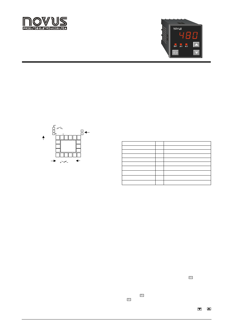
Figure 1 shows the electrical terminals of the controller.
1
2
3
4
5
6
7
8
9
10
11
12
13
14
15
18
17
16
POWER
AC/DC
15-30V
85-264V
SENSOR INPUT
AL2
OUT-B
OUT-A
PULSE
4-20mA
RELAY OUTPUT
PULSE OUTPUT
4-20mA OUTPUT
POWER
ALARM 2
CONTROL
OUTPUT
OR ALARME 1
Figure 1 - Electrical connections
2. SPECIFICATIONS
2.1. GENERAL
•
Dimensions: 48x48x106mm (1/16 DIN).
•
Panel cut-out: 45,5x45,5mm
•
Weight: 140g (1 relay), 160g (3 relays)
•
Power: 85 to 264Vdc/ac, 50/60Hz, 3VA max. Optional: 15
to 30Vdc/ac
•
Operation: 0 to 55
°
C, humidity 20 to 85%
2.2. CONTROL
OUTPUT
•
Relay output: SPST (U type) relay. Maximum current
3A/250Vac.
•
Voltage pulse output: 5Vdc/20mA
Both outputs are available in the basic model and the desired
main control output is user selected via keyboard (refer to “
Cntr
Cntr
Cntr
Cntr
“ prompt). The remaining output can then be used as an
alarm output.
In case of sensor break or failure an error "Erro
Erro
Erro
Erro
" message is
displayed and the control output is turned off.
2.3. ALARM
OUTPUTS
•
Alarm Output 1: SPST relay 3A/250Vac or 5Vdc/20mA
pulse
•
Alarm Output 2: SPST relay 3A/250Vca (optional)
2.4. POWER
Mains power is connected to terminals 5 and 6. Check the upper
side of the housing for proper power indication.
2.5. TEMPERATURE SENSOR INPUT
•
Pt100: 3-wire connection. Excitation current: 170
µ
A
•
Thermocouple input impedance: 10M
Ω
•
A/D converter resolution: 15000 steps
•
Sampling rate: 10 measurements per second
•
Accuracy: 0.2% of full scale for Pt100 and 0.25% of full
scale
±
1°C for T/C
Thermocouples are connected to terminals 8 and 9 with positive in
terminal 8.
Pt100 sensors are connected to terminals 7, 8 and 9, as indicated in
figure 1. For full compensation of cable resistance only cables with
equal wire electrical resistance should be used.
Table 1 shows the sensor types accepted and their respective
codes. via keyboard.
TYPE CODE
RANGE
J
0
0
0
0
-50 to 760°C (-58 to 1400°F)
K
1
1
1
1
-90 to 1370°C (-130 to 2498°F)
S
2
2
2
2
0 to 1760°C (32 to 3200°F)
Pt100 (Resolution 0,1°C)
3
3
3
3
-199.9 to 530.0°C (-199.9 to 986.0°F)
Pt100 (Resolution 1°C)
4
4
4
4
-200 to 530°C (-328 to 986°F)
T
5
5
5
5
-100 to 400 °C (-148 to 752°F)
E
6
6
6
6
-30 to 720°C (-22 to 1328°F)
N
7
7
7
7
-90 to 1300°C (-130 to 2372°F)
R
8
8
8
8
0 to 1760°C (32 to 3200°F)
Table 1 - Sensor types, codes and ranges
3. CONFIGURATION AND OPERATION
Prior to first operation the controller should be fully configured. The
user must set basic parameters as temperature type (“TYPE
TYPE
TYPE
TYPE
”), the
desired control set point (“ SP
SP
SP
SP
“), the alarms set points (“SPA1
SPA1
SPA1
SPA1
” and
“SPA2
SPA2
SPA2
SPA2
”), etc.
3.1. PARAMETERS FLOW CHART
The programming parameters are organized in 4 different sets or
levels:
•
Operation level
•
Alarms and tuning level
•
Configuration level
•
Calibration level
At power up the controller displays a prompt at the Operation Level
and remains in this level while under normal operation.
The other levels are only accessed when a change of parameters is
necessary (except for Set Point change). To reach these other
parameters the user must keep the INDEX Key ( ) pressed for
about three seconds. After this time the controller will show the first
parameter of the next level. By keeping the INDEX key pressed for
another 3 seconds the next level will be accessed.
Release the
key when the desired level is reached. Press once
the
to go to the next prompt in the same level.
When a parameter is shown the display will alternate its name and
value. The value can then be changed by pressing the
or
key.