NOVUS N480I User Manual
Erro
5.1
ALARM INITIAL BLOCKING
Alarm blocking at power-up inhibits the relay alarm to trip when the unit is first energized. The alarm will only
trip after the process variable reaches a new alarm situation.
Error alarm shows sensor defects or not properly connected.
6
PROBLEMS WITH THE CONTROLLER
Connection and configuration errors state for most of the problems in using the controller. A final revision of
parameters will save time and further losses.
Error messages are displayed to help the user to identify possible problems.
:
Process temperature is below the selected sensor range.
:
Process temperature is above the selected sensor range
Erro
:
Controller or sensor error. Example: Broken thermocouple or Pt100. Pt100 badly
connected, short-circuited or high cable resistance.
6.2
ELECTRONIC SERIAL NUMBER VISUALIZATION
To read the 8-digit serial number go to the Operation Level and press the
key for 3 seconds. The display
will show the first 4 digits. Then keep the
key pressed for 3 seconds and the display will show the last 4
digits.
FIRST 4 DIGITS
SERIAL NUMBER
LAST 4 DIGITS
When powering the unit the display will show the software version for a few seconds.
7
PRODUCT IDENTIFICATION
The label attached to the controller case identifies the model and the optional present in the product, as
described below:
MODEL: N480I – A – B, where:
A: Outputs:
RP OUT A = Relay and OUT B = Relay
RF OUT A = Relay and OUT B = 24Vdc auxiliary supply
B. Voltage rating:
blank (100-240 Vac/dc) or 24V (24 Vac/dc)
8
TECHNICAL ASSISTANCE
If you encounter a problem with your controller, review the configuration with regard to inputs, outputs,
alarms, etc. If the problem persists, contact your supplier or Novus at [email protected].
MICROPROCESSOR BASED TEMPERATURE
INDICATOR
N 4 8 0 I - V3.1x
OPERATING MANUAL
1
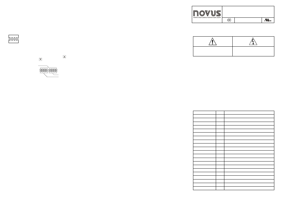
SAFETY SUMMARY
The symbols below are used on the equipment and throughout this document to draw the user’s attention to
important operational and safety information.
CAUTION or WARNING:
Read complete instructions prior to installation
and operation of the unit.
CAUTION or WARNING:
Electrical Shock Hazard
All safety related instructions that appear in the manual must be observed to ensure personal safety and to
prevent damage to either the instrument or the system. If the instrument is used in a manner not specified by
the manufacturer, the protection provided by the equipment may be impaired.
2
SPECIFICATIONS
•
Dimensions: 48 x 48 x 110 mm (1/16 DIN). Panel cut-out: 45,5 x 45,5 mm. Weight: 150 g (max.);
•
Power: 100 to 240 Vac / dc (
±
10 %), 50 / 60 Hz or 24 Vdc / ac (
±
10 %); Max. Consumption: 9 VA;
•
Pt100:
α
=385. 3-wire connection. Excitation current: 0.170 mA;
•
Accuracy: 0.2 % of full scale for Pt100 and 0,25 % of full scale
±
1 °C for T/C
•
Thermocouple input impedance: 10 M
Ω
•
A/D converter resolution: 15000 steps
•
Sampling rate: 10 measurements per second
•
Environmental conditions: 5 to 50
°
C; Relative humidity (maximum): 80 % up to 30 ºC. For
temperatures above 30 ºC, decrease 3 % per ºC. Installation category II. Pllution degree 2. Altitude <
2000 m.
•
Front panel: Polycarbonate UL94 V-2; Back panel:ABS + PC UL94 V-0
•
EMC: EN 61326-1:1997 and EN 61326-1/A1:1998
•
SAFETY: EN 61010-1: 1993 e EN 61010-1/A2: 1995
INPUT TYPE
CODE
RANGE
Termocouple J
0
0
0
0
-50 to 760 °C (-58 to 1400 °F)
Termocouple K
1
1
1
1
-90 to 1370 °C (-130 to 2498 °F)
Termocouple T
2
2
2
2
-100 to 400 °C (-148 to 752 °F)
Termocouple E
3
3
3
3
-30 to 720 °C (-22 to 1328 °F)
Termocouple N
4
4
4
4
-90 to 1300 °C (-130 to 2372 °F)
Termocouple R
5
5
5
5
0 to 1760 °C (32 to 3200 °F)
Termocouple S
6
6
6
6
0 to 1760 °C (32 to 3200 °F)
Pt100 (Resolution 0.1 °C)
7
7
7
7
-199.9 to 530.0 °C (-199.9 to 986.0 °F)
Pt100 (Resolution 1 °C)
8
8
8
8
-200 to 530 °C (-328 to 986 °F)
4 to 20 mA
9
9
9
9
Linearized J. Maximum range -110 to 760 °C
4 to 20 mA
10
10
10
10
Linearized K. Maximum range -150 to 1370 °C
4 to 20 mA
11
11
11
11
Linearized T. Maximum range -160 to 400 °C
4 to 20 mA
12
12
12
12
Linearized E. Maximum range -90 to 720 °C
4 to 20 mA
13
13
13
13
Linearized N. Maximum range -150 to 1300 °C
4 to 20 mA
14
14
14
14
Linearized R. Maximum range 0 to 1760 °C
4 to 20 mA
15
15
15
15
Linearized S. Maximum range 0 to 1760 °C
4 to 20 mA
16
16
16
16
Linearized Pt100. Max. range -199.9 to 530.0 °C
4 to 20 mA
17
17
17
17
Linearized Pt100. Max. range -200 to 530 °C
0 to 50 mV
18
18
18
18
Linear. Programmable range from -1999 to 9999
4 to 20 mA
19
19
19
19
Linear. Programmable range from -1999 to 9999
0 to 10 V
20
20
20
20
Linear. Programmable range from -1999 to 9999
Table 1 – Types of sensors accepted by the indicator