Electrical installation – NOVUS DigiGate Profibus User Manual
Page 3
DigiGate Profibus
NOVUS AUTOMATION
3/10
ELECTRICAL INSTALLATION
Recommendations for installation
•
When mounting the device on the DIN rail be sure to let a space of approx. 1 cm between the adjacent devices, in order
to allow heat dissipation and avoid overheating of the product.
•
Input and communication signal conductors must go through the system base separated from electrical network
conductors, if possible, in grounded conduits.
•
The power supply for the instruments must be provided from a network appropriate for instrumentation.
•
In control and monitoring applications it is essential to consider what may occur in case of failure of any part of the
system.
•
It is recommended using RC FILTERS (47
Ω
and 100 nF, series) in parallel with contactor and solenoid coils which
are next to or connected to the DigiGate.
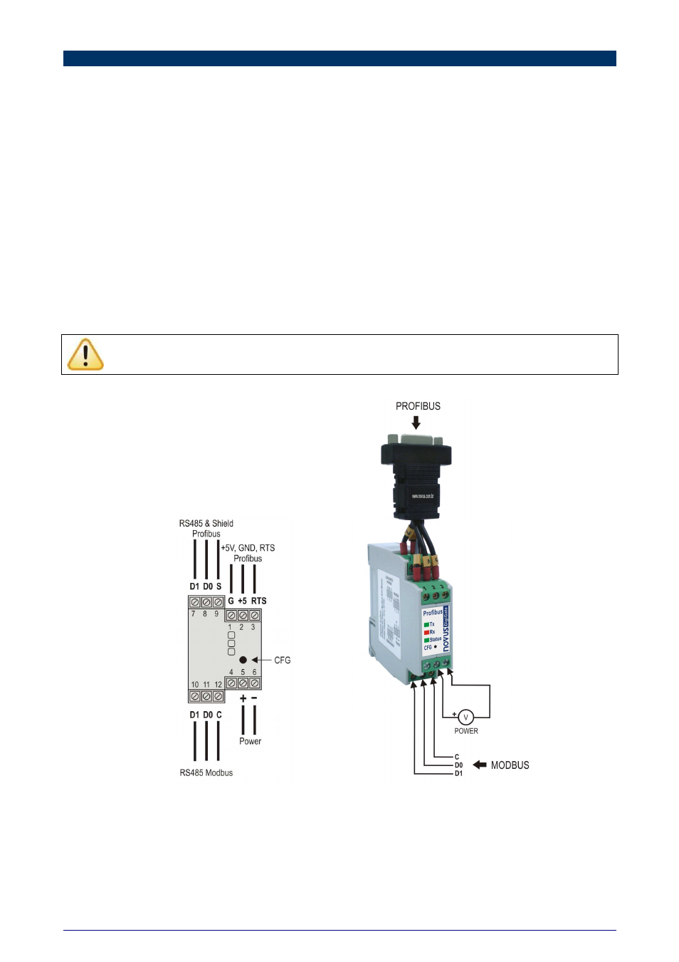
Electrical Connections
Figure 2 shows the necessary electrical connections. The terminals 1, 2, 3, 7, 8 and 9 are intended for the Profibus
network connections (being mandatory only the connections at the terminals 7 and 8), 5 and 6 are for the power supply
of the module, while 10, 11 and 12 are intended for communication with the Modbus network. For obtaining better
electrical contact to the connectors, it is recommended using pin shape terminals at the end of the conductors. For direct
wire connection the recommended minimum gauge is 0.14 mm², not exceeding 4.00 mm².
Attention when connecting the power supply terminals to the DigiGate. If the positive conductor of the power
source is fastened, even momentarily, at any of the other terminals, the device may be damaged.
Figure 2 – Electrical connections