Serial communication, Registers – NOVUS FieldLogger Register User Manual
Page 5
FieldLogger Register
NOVUS AUTOMATION
5/8
SERIAL COMMUNICATION
The logger has a master-slave asynchronous serial communication
interface RS485 to communicate with a supervisory computer
(master). The logger is always the slave.
Communication always start with the master, which sends a
command to the slave address with whom it wants to communicate.
The addressed slave undertakes the command and sends the
corresponding answer to the master.
The logger also accepts broadcast commands.
Note: Recommended cables for serial communication are 3 x 24
AWG + shield. This way the shield can be grounded while cables are
used for signals.
FEATURES
Signals supported by RS485 standard. We recommend reading the
document “Basic concepts of RS485 and RS422” available in the CD
that is delivered with the equipment.
Communication signals are electrically isolated from the rest of the
device, with configurable speed of 1200, 2400, 4800, 9600, 19200
and 57600 bps.
Number of data bits: 8.
Parity: none, odd or even.
Number of stop bits: 1 (odd or even parity) or 2 (no parity).
Response delay: up to 20 ms after command is received.
Protocol: Modbus RTU, available in most supervisory software of the
industry.
RS-485 signals are:
D1 D D+ B Bidirectional data line
Terminal 17
D0
D:
D- A Reversed bidirectional data
line
Terminal 18
C
GND
Optional connection that
enhances
the
communication performance
Terminal 16
PHYSICAL SPECIFICATIONS
•
Three-wire connection (2 data wires and 1 common) between 1
master and up to 247 instruments (maximum of 31 per network
segment) in bus topology.
•
Shielded cable, 3 x 24 AWG, with shield grounded in one end;
•
16 pF capacitance at every 30 m;
•
Typical impedance: 120 Ohms;
•
Maximum length 1200 m;
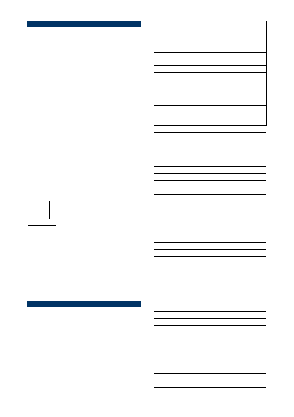
REGISTERS
The logger configurable parameters are organized in a Table of
Registers. The block reading command makes possible to read
multiple registers with the same request.
The configuration software, however, makes such table not
necessary, once it reads and writes in all registers that require
configuration. Each parameter in the table is a word of 16 bits.
The available Modbus command for the reading operation is the
following:
03 - Read Holding Register
This way, it is worth reporting the following registers, which are
equivalent to the holding registers (reference 4X):
HOLDING
REGISTERS
DESCRIPTION
0000
Current value of channel 1
0001
Current value of channel 2
0002
Current value of channel 3
0003
Current value of channel 4
0004
Current value of channel 5
0005
Current value of channel 6
0006
Current value of channel 7
0007
Current value of channel 8
0008
Informs alarm status
0009
Reserved: Informs general status
0010
Informs channels 1 and 2 status
0011
Informs channels 3 and 4 status
0012
Informs channels 5 and 6 status
0013
Informs channels 7 and 8 status
0014
Current time (seconds and minute)
0015
Current time (hour and day)
0016
Current time (month and year)
0017
Channel 1 configuration
0018
Channel 2 configuration
0019
Channel 3 configuration
0020
Channel 4 configuration
0021
Channel 5 configuration
0022
Channel 6 configuration
0023
Channel 7 configuration
0024
Channel 8 configuration
0076
Bytes 0 and 1 of the title string
0077
Bytes 2 and 3 of the title string
0078
Bytes 4 and 5 of the title string
0079
Bytes 6 and 7 of the title string
0080
Bytes 8 and 9 of the title string
0081
Bytes 10 and 11 of the title string
0082
Bytes 12 and 13 of the title string
0083
Bytes 14 and 15 of the title string
0084
Bytes 0 and 1 of channel 1 string (tag)
0085
Bytes 2 and 3 of channel 1 string (tag)
0086
Bytes 4 and 5 of channel 1 string (tag)
0087
Bytes 6 and 7 of channel 1 string (tag)
0088
Bytes 0 and 1 of channel 2 string (tag)
0089
Bytes 2 and 3 of channel 2 string (tag)
0090
Bytes 4 and 5 of channel 2 string (tag)
0091
Bytes 6 and 7 of channel 2 string (tag)
0092
Bytes 0 and 1 of channel 3 string (tag)
0093
Bytes 2 and 3 of channel 3 string (tag)
0094
Bytes 4 and 5 of channel 3 string (tag)
0095
Bytes 6 and 7 of channel 3 string (tag)
0096
Bytes 0 and 1 of channel 4 string (tag)
0097
Bytes 2 and 3 of channel 4 string (tag)
0098
Bytes 4 and 5 of channel 4 string (tag)
0099
Bytes 6 and 7 of channel 4 string (tag)
0100
Bytes 0 and 1 of channel 5 string (tag)
0101
Bytes 2 and 3 of channel 5 string (tag)
0102
Bytes 4 and 5 of channel 5 string (tag)
0103
Bytes 6 and 7 of channel 5 string (tag)