NOVUS N1500G User Manual
Page 4
Indicator N1500G
NOVUS AUTOMATION
4/5
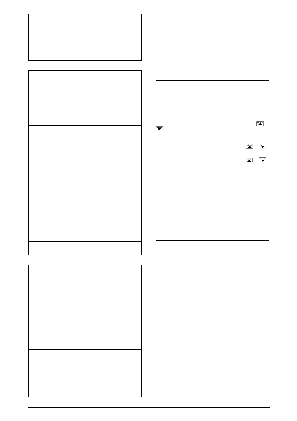
Al1t1
Al1t2
Al2t1
Al2t2
Al3t1
Al3t2
Al4t1
Al4t2
Time Alarms
The user can set delayed or sequential alarms as
shown in table 3 by defining times T1 and T2.
To disable this function just set zero for T1 and T2.
7.3.
FUNCTION CYCLES
f.fvnc
F KEY FUNCTION - Options are
oFF - Key no used.
Hold - Hold PV
AL.oFF -
Alarm disabled
rESEt - Resets Peak and Valley
PHoLd - Peak Hold
tArE - Tare zeroing
These functions are described in item 5.2.
Dig.in
Digital Input Function - The same function
available for the F key:
oFF - Hold - AL.oFF - rESEt - PHoLd - tArE
Refer to item 5.2.
filtr
Input Digital Filter - Adjustable from 0 to 20, this is
used to reduce instability of the measured value.
0 means the filter is off and 20 means maximum
filtering. The higher the filter value the lower is the
measured value response.
ofset
Display Offset - This a value which is added to the
PV to offset any measurement deviation or sensor
error. The offset is shown directly in the programmed
engineering unit.
For °F measurements the null reference is at 32°F.
bavd
Baud Rate - Serial digital communication speed in
bps.
Programmable: 1200, 2400, 4800, 9600 and 19200
bps.
Adres
Communication Address - A number which
identifies the instrument in a multidrop network.
7.4.
CONFIGURATION CYCLE
In.typ
Input Type - Selects the input signal or sensor type
to be connected to the PV terminals. Refer to table
1.
Changing this parameter will change all other
parameters related to PV and alarms, therefore it
should be the first parameter to be set.
Dp.pos
Decimal Point Position - Defines the decimal point
position in the displayed value. This applies to linear
input types 0 to 50mV, 4 to 20mA and 0 to 5V as
selected at the “in.tYP” prompt.
Vnit
Temperature Unit - Selects °C or °F indication. This
prompt is not shown for input types 0 to 50mV, 4 to
20mA and 0 to 5V as selected at the “in.tYP”
prompt.
s.root
Square Root - This prompt is only shown for input
types 0 to 50mV, 4 to 20mA and 0 to 5V as selected
at the “in.tYP” prompt.
Set “YES” and the square root will be applied to the
measured value within the limits programmed in
“in.LoL” and “in.HiL”.
The display will show the low limit value should the
input signal be below 1% of the range.
In.lol
Input Low Limit - Sets the low limit for input type 0
to 50 mV, 4 to 20 mA or 0 to 5 V. When the PV
Retransmition is used this limit defines the
corresponding 4 mA (or 0 mA) in relation to the input
value.
In.kil
Input High Limit - Sets the high limit for input type 0
to 50 mV, 4 to 20 mA or 0 to 5 V. When the PV
Retransmition is used this limit defines the
corresponding 20 mA in relation to the input value.
S(ale
Scale Factor - Multiplies the displayed value by 10
to increase measured range.
Ovt.ty
Analog Output Type - Selects the analog output
type to either 0 to 20 mA or 4 to 20 mA.
8.5
CALIBRATION CYCLE
All input types are factory calibrated and field calibration is
seldom necessary. Should it be required the calibration should
only be done by experienced personnel.
If this cycle is accidentally accessed do not touch the
or
keys. Just press the index key and go through all cycles
until the display shows the main or operation menu.
In.lo(
Input Low Calibration - Sets the Process Variable low
calibration (offset). Several key strokes at
or
might be necessary to increment one digit.
In.ki(
Input Hi Calibration - Sets the Process Variable span
calibration (gain). Several key strokes at
or
might be necessary to increment one digit.
Ov.lo(
Analog Output Low Calibration - Sets the analog
current output low calibration (offset).
Ov.Ki(
Analog Output Span Calibration - Sets the analog
current output high calibration (span).
(J lo
Cold Junction Calibration - Allows the user to
adjust the this calibration directly in degrees for
achieving best results with thermocouples.
k.type
Hardware Type - These parameters adapts the
software to the hardware available and should not be
changed by the user.
0 - No options
1 - With alarms 3 and 4
2 - With digital input
8.
DIGITAL COMMUNICATION
The indicator can be supplied with an asynchronous RS-485 digital
communication interface for master-slave connection to a host
computer (master).
The indicator works as a slave only and all commands are started by
the computer which sends a request to the slave address. The
addressed unit processes the command and sends back the answer.
Broadcast commands (addressed to all indicator units in a multidrop
network) are accepted but no response is generated.
8.1.
CHARACTERISTICS
-
RS-485 compatibility with two-wire bus from the host to up to 31
slaves in a multidrop network topology.
-
Up to 247 units can be addressed by the MODBUS RTU protocol.
-
Maximum network distance: 1200 m.
-
Time of indicator disconnection: Maximum of 2 ms after the
delivery of the last byte.
-
Communication signals electrically isolated from the rest of the
instrument.
-
Baud rate: 1200, 2400, 4800, 9600, 19200, 38400 or 57600 bps.
-
Number of data bits: 8, without parity or even parity
-
Number of stop bits: 1
-
Time to start response transmission: 100 ms maximum delay after
acknowledging the command.
-
Protocol: MODBUS (RTU)