NOVUS N1500G User Manual
Page 3
Indicator N1500G
NOVUS AUTOMATION
3/5
5.2.
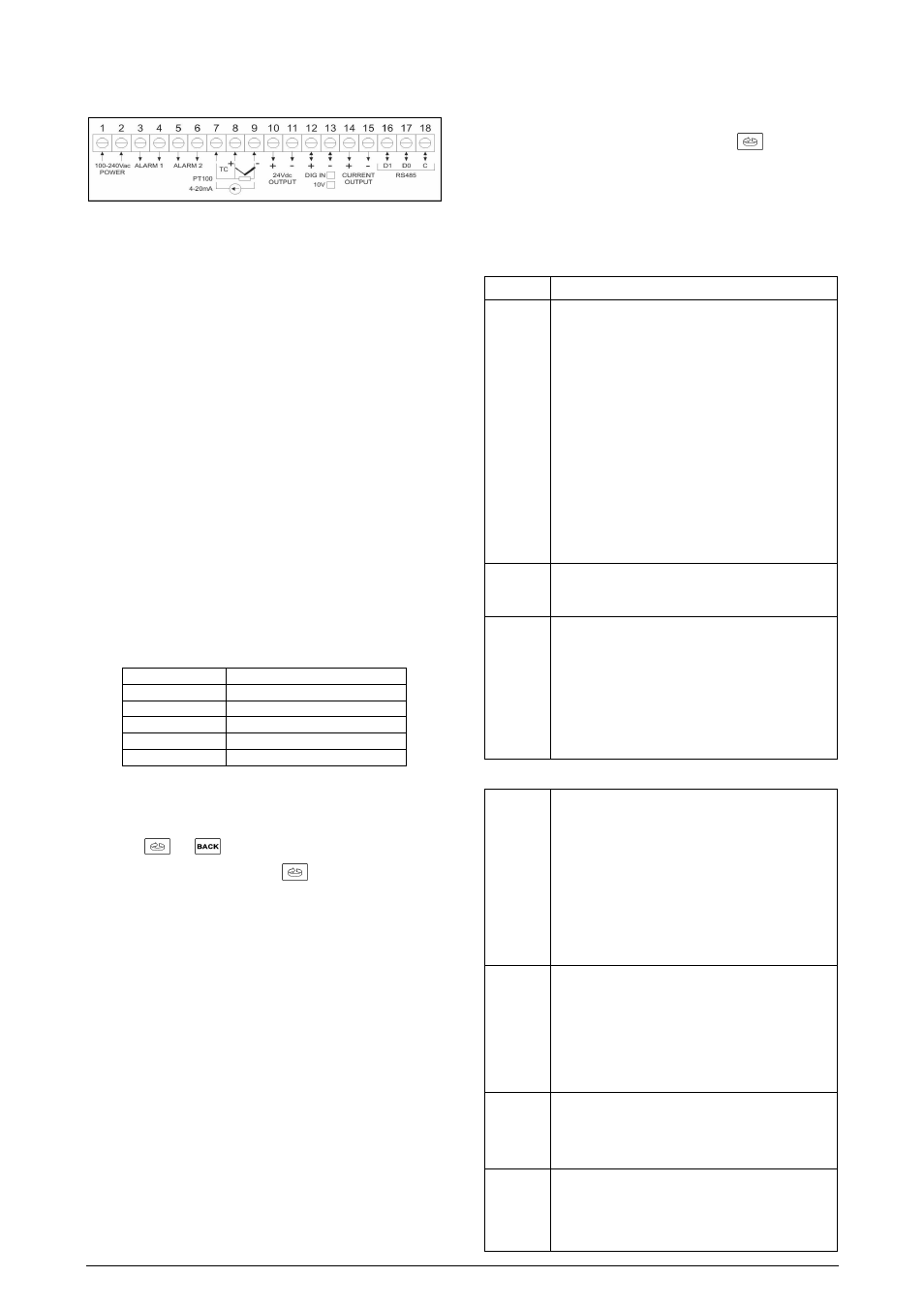
ELECTRICAL CONNECTIONS
The internal electronics can be removed from the front panel without
any cable disassembly. The input signals and power connections are
shown in Figure 3.
Figure 3 - Back panel terminals
5.2.1.
Recommendations for Installation
•
Input signal wires should be laid out away from power lines and
preferably inside grounded conduits.
•
Instrument mains should be suitable for this purpose and wires
should not be shared with high consumption motors and inductors.
•
RC filters (47
Ω
and 100nF) are highly recommended for valve and
contactor coils, etc.
5.2.2.
Sensor or input signal connection
These connections should be properly done and terminals must be
well tightened. Thermocouples must be installed with proper
extension or compensation cables.
Pt100 RTDs must be 3-wire connected and the wires connected
should have the same electrical resistance (same wire gauge) for
correct cable length compensation. Four-wire RTDs can be
connected by disconnecting the fourth wire. Two-wire RTDs can be
connected by shortening terminals 7 and 8 and connecting the Pt100
to terminals 8 and 9.
6.
OPERATION
For best results this indicator requires correct setting of parameters
as input type (T/C, Pt100, 4-20 mA, etc), alarms actuation point,
alarm function, etc.
These parameters are divided in five levels or groups of parameters
which we will refer to as CYCLES.
Cycle
Access
1- Work
free access
2- Alarms
3- Functions
4- Configuration
reserved access
5- Calibration
Table 4 - Parameters Cycles
The work cycle has free access. All other cycles require a certain
combination of key strokes to be accessed. The combination is:
and
keys pressed simultaneously
Within a certain cycle just press
to go to the following
parameters. At the end of each cycle the display will go back to the
work cycle.
At the desired prompt just press the MAX or MIN key to change this
parameter accordingly.
All changes are recorded in non-volatile memory as we move to next
prompt. After 25 seconds with no key pressed the indicator will return
to the measuring cycle (work cycle).
6.1.
CYCLE PROTECTION
The values of parameters of a certain cycle can be protected against
non-authorized users.
The protected parameters can still be viewed but can not be
changed.
To protect a cycle just press the BACK and MAX keys for 3 seconds
at the beginning of the referred cycle. To unlock this cycle just press
the same keys again for 3 seconds.
The display will briefly blink confirming that the locking or
unlocking of the cycle.
7.
PROGRAMMING THE INDICATOR
7.1.
WORK CYCLE
This is the first and main cycle. At power up the indicator will display
the Process Variable (PV). The alarm setpoints are also displayed at
this cycle. To run through this cycle just press the
key.
Whenever an alarm is set with differential function the respective
alarm setpoint is blocked (SP.AL1, SP.AL2, ...) and the display
shows “diF” to advise the operator that this is a configuration
parameter and that the respective deviation value must be
programmed at the Alarms Cycle. The “AL.rEF” prompt will be
displayed showing the reference value for the alarm with differential
function.
TELA
PARAMETER DESCRIPTION
8.8.8.8.8.
Measure Shows the measured variable. For Pt100
or thermocouples the display will show the absolute
temperature value.
For 4-20 mA, 0-50 mV and 0-5 V inputs the display
shows the values defined in the in.LoL” and “in.HiL”
prompts.
With the hold function programmed the display
shows the frozen variable and alternates with the
message “HoLd”.
Likewise, with Peak Hold function programmed the
high limit is displayed with the “P.HoLd” prompt
alternately.
Should any fault situation occur the indicator will
display an error message which can be identified at
item 11 of this manual.
Al.ref
Differential Alarm Reference Value - This prompt
is shown only when there is an alarm programmed
with differential function.
Sp.al1
Sp.al2
Sp.al3
Sp.al4
Set Points of Alarms 1, 2, 3 and 4 - Defines the
operation point of each alarm programmed with “Lo”
or “Hi” function.
Note: When the alarms are programmed with
differential function, the alarm setpoint cannot be
changed at this cycle and a “diF” message will be
shown. The SP differential (deviation) value is set at
the Alarm Cycle.
7.2.
ALARM CYCLE
fV.al1
fV.al2
fV.al3
fV.al4
Alarm Function - Defines the alarms 1, 2, 3 and 4
function, as defined in item 4.1
oFF
: Alarm off
iErr
: Broken or Shorted Sensor
Lo
: Low value
Hi
: High value
DiFL
: Differential low
DiFH
: Differential high
DiF
: Differential
Df.al1
Df.al2
Df.al3
df.al4
Differential SP for Alarms 1, 2, 3 and 4 - Defines
the deviation value from the alarm setpoint in relation
to the Reference Value defined in the “ALdiF”
prompt.
Note: This value cannot be changed at this cycle for
alarms with non-differential function and the “AbS” is
then displayed.
Ky.al1
Ky.al2
Ky.al3
ky.al4
Alarm Hysteresis
This is the difference from the measured value to the
point where the alarm is turned ON and OFF.
Bl.al1
Bl.al2
Bl.al3
bl.al4
Alarm Blocking
Should any alarm condition occur, each alarm can
be disabled when energizing the indicator. Refer to
item 4.3.