Avto, Pr n, Atvn – NOVUS N1100HC User Manual
Page 4: Xyst, Ovll, Ovxl, Sfst, Sp.a1, Sp.a2, Sp.a3
N1100HC Controller
NOVUS AUTOMATION
4/7
5.7
SOFT-START
Defines the time interval for the output to reach its maximum value
(100 %). The soft-start value is programmed in the “SfSt
SfSt
SfSt
SfSt”
parameter.
The Soft-start is important to processes which require a slow rate of
increase in the applied power, preventing the application of 100% of
the power at start-up.
The control output is primarily determined by the PID loop control;
the Soft-start simply limits this output. See also parameters “o1ll
o1ll
o1ll
o1ll”
and “o1kl
o1kl
o1kl
o1kl”.
5.8
SQUARE ROOT EXTRACTION
Available when input type 19 is selected. The indicator displays the
square root of the current signal input applied to terminals 10 and 11.
6
INSTALLATION
Insert the unit into the panel cut-out and slide the mounting clamp
from the rear to a firm grip at the panel.
6.1
ELECTRICAL CONNECTIONS
0-20mA OR 4-20mA OUTPUT
PULSE OUTPUT
RELAY
OUTPUTS
SERIAL COMMUNICATION (OPTIONAL)
RELAY OR I/O DIGITAL (OPTIONAL)
D1
I/
O
4
D0
G
N
D
C
SENSOR INPUT
T/C, RTD
4-20mA, 0-50mV, 0-5V
POWER
mA
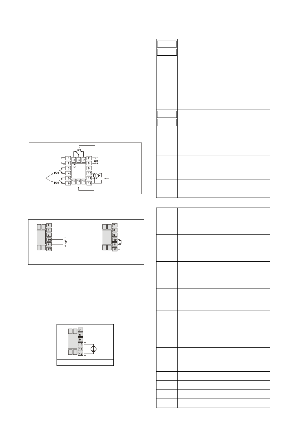
Figure 2 - Backpannel terminals
•
Thermocouple and voltage (Volts and mV) input connect as in
Figure 3.
T/C, 0-50mV, 0-5V
Pt100
Figure 3 – thermocouple and Voltage
wiring
Figure 4 - RTD input wiring
•
RTD (Pt100)
Figure 4 shows the Pt100 wiring, for 3 conductors. Terminals 10,
11 and 12 must have the same wire resistance for proper cable
length compensation. For 2 wire Pt100, short circuit terminals 11
and 12.
•
4-20 mA
Refer to Figure 5. (The controller provides an internal electronic
shunt for the input current. No changes in the circuit are
necessary).
4-20mA
Figure 5 – Input current wiring
•
Digital Input
Refer to Figure 8 on how to use channels I/O3, I/O4 or I/O5 as
digital inputs. See also explanations on section 5.2
7
CONFIGURATION PARAMETERS
7.1
OPERATION CYCLE
PV Indication
(Red)
SV Indication
(Green)
PV AND SV INDICATION: The status display shows
the present value of PV (Process Variable). The
parameter display shows SV (Set Variable).
The status display shows “- - - -“ whenever PV
exceeds the maximum range or there is no signal at
the input. In case of hardware error the status display
will show Ern
Ern
Ern
Ern, where n is the error code.
avto
avto
avto
avto
CONTROL MODE: YES indicates automatic control
mode (closed loop, PID or ON/OFF).
NO
indicates
manual control mode (open loop). Bumpless transfer
from auto
↔
to manual mode is available. If in doubt
program YES.
PV Indication
(Red)
MV Indication
(Green)
MANIPULATED VARIABLE VALUE (MV): The upper
display shows PV value and the lower display shows
the percentage of MV applied to the control output.
When in manual control the MV value can be
manually changed. When in auto mode the MV value
can only be viewed.
To distinguish the MV display from the SV display,
the MV is shown flashing intermittently.
Pr n
Pr n
Pr n
Pr n
RAMP AND SOAK PROGRAM SELECTION: Selects
the ramp and soak program to be executed (4
programs possible). Refer to chapter 7 for R&S
description.
rvn
rvn
rvn
rvn
CONTROL ENABLE: YES means that the control
output and alarms are enabled and NO means they
are disabled.
7.2
AUTO TUNING CYCLE 1
atvn
atvn
atvn
atvn
AUTO-TUNE: YES enables the auto tuning of the
PID parameters and NO disables it.
Pb1
Pb1
Pb1
Pb1
PROPORTIONAL BAND: Percentage of maximum
input span. Select zero for ON/OFF control.
xyst
xyst
xyst
xyst
CONTROL HYSTERESIS (in engIneering. units): This
parameter is only shown for ON/OFF control (Pb=0).
‘ ir‘
‘ ir‘
‘ ir‘
‘ ir‘
INTEGRAL RATE: Integral time constant in
repetitions per minute (Reset).
dt
dt
dt
dt
DERIVATIVE TIME: Derivative time constant, in
seconds.
(t1
(t1
(t1
(t1
CYCLE TIME: PWM period in seconds. Can only be
viewed if proportional band is other than zero.
act
act
act
act
CONTROL ACTION: For Auto Mode only.
•
Reverse Action
rE
rE
rE
rE
usually used for heating.
•
Direct Action
dir
dir
dir
dir
usually used for cooling.
ovll
ovll
ovll
ovll
OUTPUT LOW LIMIT: minimum percentage value for
MV (Manipulated Variable) when in automatic control
and PID. Default value: 0.0 %
ovxl
ovxl
ovxl
ovxl
OUTPUT HIGH LIMIT: Maximum percentage value
for MV when in automatic control and PID. Default
value: 100.0 %
sfst
sfst
sfst
sfst
SOFT START: Time in seconds during which the
controller limits the MV value progressively from 0 to
100 %. It is enabled at power up or when the control
output is activated. If in doubt set zero.
Sp.a1
Sp.a1
Sp.a1
Sp.a1
ALARM 1 PRESET: Tripping point for alarm 1.
Sp.a2
Sp.a2
Sp.a2
Sp.a2
ALARM 2 PRESET: Tripping point for alarm 2.
Sp.a3
Sp.a3
Sp.a3
Sp.a3
ALARM 3 PRESET: Tripping point for alarm 3.
Sp.a4
Sp.a4
Sp.a4
Sp.a4
ALARM 4 PRESET: Tripping point for alarm 4.