NOVUS N1100HC User Manual
Page 3
N1100HC Controller
NOVUS AUTOMATION
3/7
CODE
I/O Type
I/O Function
0
0
0
0
Digital Output
Digital Output to be set by the serial comm.
1
1
1
1
Digital Output
Alarm 1 Output
2
2
2
2
Digital Output
Alarm 2 Output
3
3
3
3
Digital Output
Alarm 3 Output
4
4
4
4
Digital Output
Alarm 4 Output
5
5
5
5
Digital Output
PWM Control Output 1
6
6
6
6
Digital Output
PWM Control Output 2
7
7
7
7
Digital Input
Automatic/Manual mode change
8
8
8
8
Digital Input
Run/Stop mode change
9
9
9
9
Digital Input
Reserved
10
10
10
10
Digital Input
Executes/Holds selected ramp and soak profile
11
11
11
11
Digital Input
Enable/Disable R&S profile 1 selection
12
12
12
12
Analog Output
4 to 20 mA Analog control output 1
13
13
13
13
Analog Output
0 to 20 mA Analog control output 1
14
14
14
14
Analog Output
4 to 20 mA PV retransmission
1
1
1
15
5
5
5
Analog Output
0 to 20 mA PV retransmission
16
16
16
16
Analog Output
4 to 20 mA SP retransmission
17
17
17
17
Analog Output
0 to 20 mA SP retransmission
18
18
18
18
Analog Output
4 to 20 mA control output 2
19
19
19
19
Analog Output
0 to 20 mA control output 2
Table 2 - I/O channel functions
•
CODE 9 - Digital input - Reserved
•
CODE 10 - Digital input - Standard for I/O5 and optional for I/O3
and I/O4.
Opened: enables R&S program
Closed: holds R&S program (the program resumes
when the contact is opened again)
•
CODE 11 - Digital input - Standard for I/O5 and optional for I/O3
and I/O4.
Selects R&S program 1.
Used to alternate between the main Setpoint and a second
Setpoint defined by the R&S program 1.
Closed: selects program 1
Opened: uses main Setpoint
•
CODES 12 to 13 - Control Output 1 (0-20 / 4-20 mA) - Available
only for I/O5.
Configures channel I/O5 to operate as control output 1 with 0-20
or 4-20 mA signal.
•
CODES 14 to 17 - Analog retransmission. Available only for
I/O5. Configures I/O5 to output a 0-20 mA or 4-20 mA analog
signal proportional to PV or SP.
•
CODES 18 to 19 – Control Output 2 (0-20 / 4-20 mA) - Available
only for I/O5.
Configures channel I/O5 to operate as control output 2 with 0-20
or 4-20 mA signal.
5.3
ALARM CONFIGURATION
The controller has 4 alarms. Only alarms 1 and 2 have front panel
lamps associated to them.
The alarms can the configured to operate in any of the nine functions
listed on Table 3.
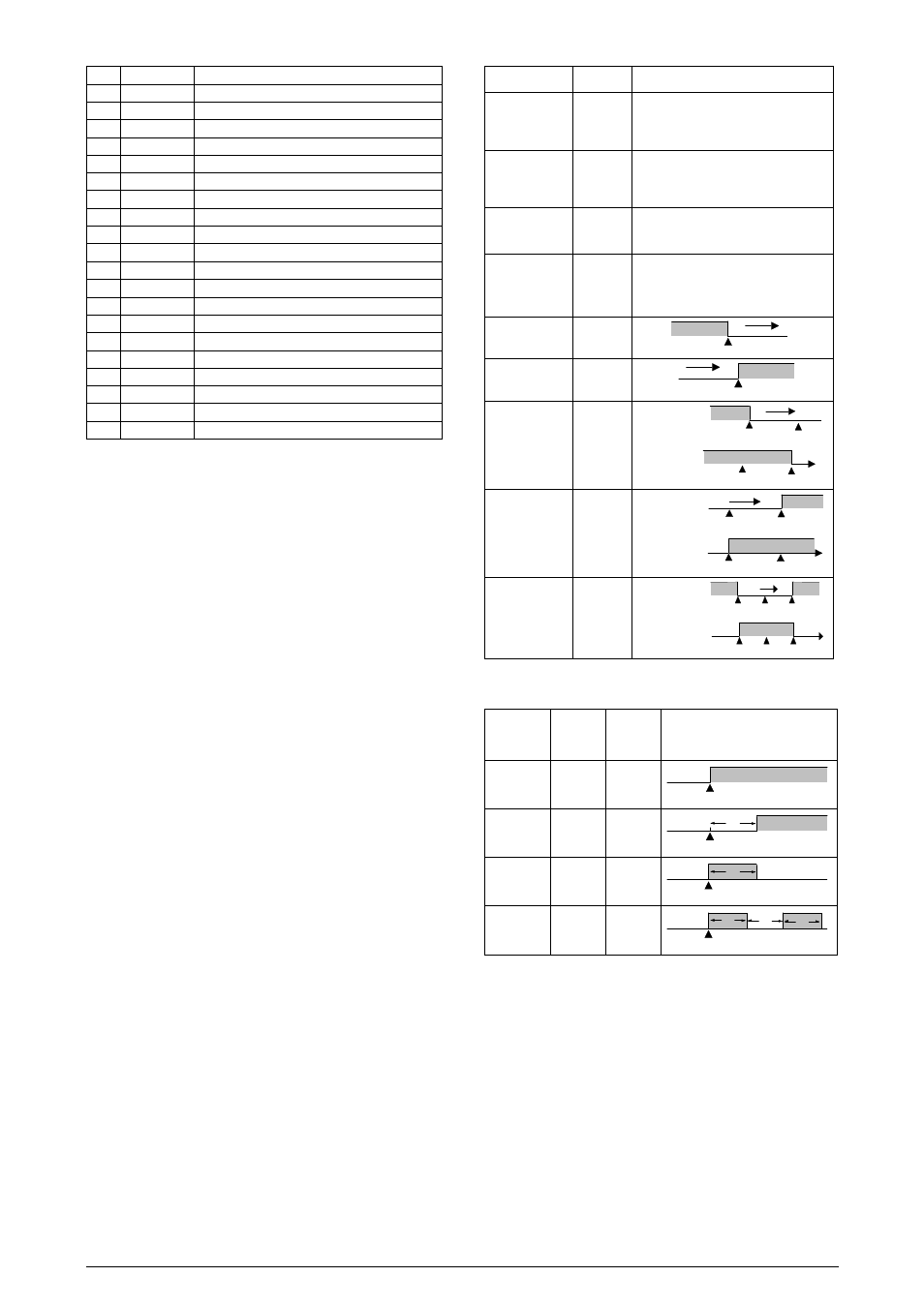
5.4
ALARM TIMER FUNCTIONS
Alarms 1 and 2 can be programmed to have timer functions. The 3
modes of operation are:
- pulse
- delayed actuation
- oscillator
The desired function can be achieved programming the parameters
“A1t1
A1t1
A1t1
A1t1”, “A1t2
A1t2
A1t2
A1t2”, “A2t1
A2t1
A2t1
A2t1” and “A2t2
A2t2
A2t2
A2t2” (see Table 4).
The LEDs associated to the alarms will light when the alarm
condition is recognized, not following the actual state of the output,
which may be temporarily OFF because of the temporization.
TYPE
PROMPT
ACTION
Disabled
off
off
off
off
No active alarm. This output can be
used as a digital output to be set by the
serial communication.
Sensor Break
(
i
nput
Err
or)
ierr
ierr
ierr
ierr
Alarm will be ON if PV sensor breaks,
input signal is out of range or Pt100 is
shorted.
Event Alarm
(
r
amp and
S
oak)
rs
rs
rs
rs
Can be activated at a specific segment
of ramp and soak program.
Heater break
detection
r
esistance
fail
rfail
rfail
rfail
rfail
Detects a heater broken condition
Lo
w Alarm
lo
lo
lo
lo
SPAn
PV
Hi
gh Alarm
ki
ki
ki
ki
SPAn
PV
LOW
Differential
difl
difl
difl
difl
positive SPAn
SV
PV
SV + SPAn
negative SPAn
SV
PV
SV + SPAn
HIGH
Differential
difk
difk
difk
difk
positive SPAn
SV
PV
SV + SPAn
negative SPAn
SV
PV
SV + SPAn
Dif
ferential
dif
dif
dif
dif
positive SPAn
SV
PV
SV + SPAn
SV - SPAn
negative SPAn
SV
PV
SV + SPAn
SV - SPAn
Table 3 - Alarm functions
Where SPAn means “SPA1
SPA1
SPA1
SPA1”, “SPA2
SPA2
SPA2
SPA2”, “SPA2
SPA2
SPA2
SPA2” and “SPA4
SPA4
SPA4
SPA4”.
Alarm
Function
T1
T2
ACTION
Normal
0
0
Alarm Event
Alarm
Output
Delayed
0
1 s to
6500 s
Alarm Event
Alarm
Output
T2
Pulse
1 s to
6500 s
0
Alarm Event
Alarm
Output
T1
Oscillator
1 s to
6500 s
1 s to
6500 s
Alarm Event
Alarm
Output
alarme
T1
T2
T1
Table 4 - Advanced Timer Alarm (for alarms 1 or 2):
5.5
ALARM INITIAL BLOCKING
The initial blocking option inhibits the alarm from being recognized if
an alarm condition is present when the controller is first energized.
The alarm will actuate only after the occurrence of a non alarm
condition followed by a new occurrence for the alarm.
The initial blocking is disabled for the sensor break alarm function.
5.6
ANALOG RETRANSMISSION OF PV AND SP
The analog output, when not used for control purposes, is available
for retransmitting the SV and SP values in 0-20 or 4-20 mA. This
analog output is electrically isolated from other inputs and outputs.
The analog output signal is scaleable, with the output range determined
by the values programmed in the parameters “SPLL
SPLL
SPLL
SPLL” and “SPkL
SPkL
SPkL
SPkL”.
To obtain a voltage output, connect a resistor shunt to the current
output terminals (terminal 7 and 8).