NOVUS TxIsoPack User Manual
Page 2
NOVUS AUTOMATION
2/3
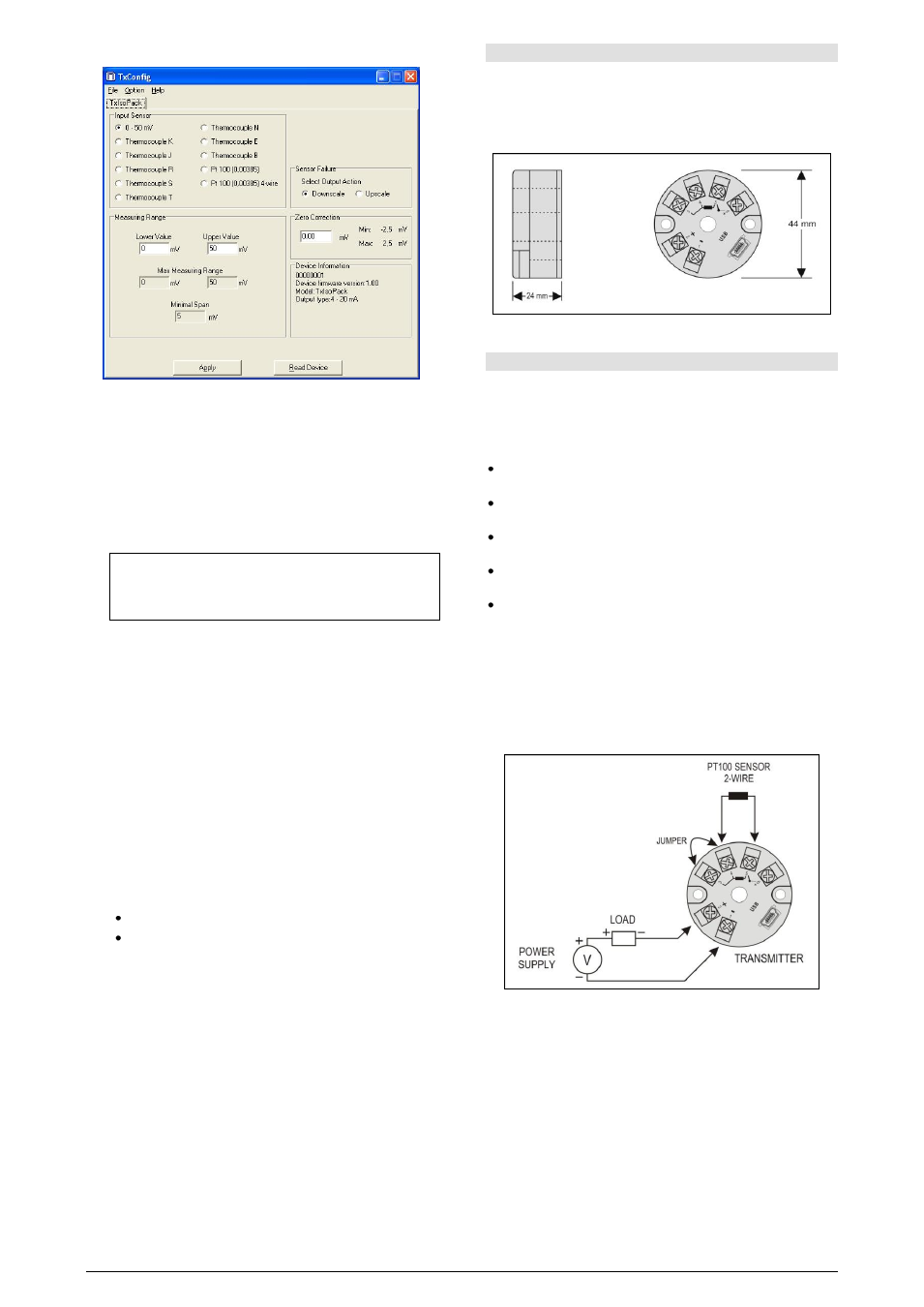
The TxConfig screen in shown in Fig. 3.
Fig. 3 – TxConfig main screen
The fields in the screen mean:
1. Input Sensor: Select the sensor to be used. See Table 1.
2. Measuring Range: Define the transmitter measurement range.
Range Lower Limit: temperature desired for a 4 mA current.
Range Upper Limit: temperature desired for a 20 mA current.
When the Lower Limit is set with a value greater than the Upper
Limit value of the output current operates from 20 to 4 mA (the
current decreases as the temperature increases).
Note: The values chosen can not exceed the Sensor Range shown
in this same field, and also may not establish a range with width
(span) smaller than the Min. Range indicated later in this same field.
See Table 1 of this guideline.
3. Sensor Failure: It establishes the output behavior, when the transmitter
indicates a failure:
Minimum: output current goes to 3.8 mA (down-scale), typically used for
refrigeration.
Maximum: output current goes to 20.5 mA (up-scale), typically used for
heating.
4. Device Information: This field contains the data identifying the
transmitter. This information must be submitted to the manufacturer for
any queries.
5. Zero Correction: It corrects small deviations presented in the transmitter
outlet, for example, when the sensor is replaced.
6. Send Configuration: It applies the new setup. Once sent, the setup will
be immediately adopted by the transmitter.
7. Read Configuration: Reads the current setup in the transmitter
connected. The screen now presents the current setup that may be
changed by the user.
Note: The factory default configuration is:
Sensor Pt100, range 0 to 100 °C, 0 °C of zero correction.
Output at maximum for the sensor failures.
Upon purchase order, the user can define a specific setup.
MECHANICAL INSTALLATION
The TxIsoPack transmitter is suitable to be installed in heads. Vibrations,
moisture and extreme temperatures, electro-magnetic interference, high
voltage and other interferences can permanently damage the unit, and could
cause error in the measured value.
DIMENSIONS:
Fig. 4 – Transmitter dimensions
ELECTRICAL INSTALLATION
Polyamide enclosure.
Section of the cable used: 0.14 to 1.5 mm².
Recommended torque in the terminal: 0.8 Nm.
RECOMMENDATIONS FOR INSTALLATION
Sensor signals conductors must go through the plant system separate
from power leads (loop), if possible in grounded conduits.
The instruments must be powered from the instrumentation power supply
circuit.
In control and monitoring applications is essential to consider what can
happen when any part of the system fails.
It is recommended the use of suppressors in contact coils, solenoids and
any inductive load.
Use compensation cables in the connections using thermocouples.
ELECTRICAL CONNECTIONS
The figures below show the electrical connections required. The terminals 3, 4,
5 and 6 are dedicated to the sensor connection. LOAD represents the 4-20 mA
current measuring device (indicator, controller, recorder, etc.)
PT100 2-WIRES
Note: When the Pt100 2-wires the terminals 3 and 4 must be interconnected,
according to the figure below.
Fig. 5 – Transmitter electrical connections (Pt100 2-wires)