NOVUS Controlador N960 User Manual
Page 3
Controlador N960
NOVUS AUTOMATION
3/4
CONFIGURATION LEVEL
type
Input Type: Selection of the type of temperature
sensor that will be used. See Table 1. This must be
the first parameter to be set up.
0
- J Thermocouple;
1
- K Thermocouple;
2
- T Thermocouple;
3
- N Thermocouple;
4
- R Thermocouple;
5
- S Thermocouple;
6
- Pt100 with a resolution of 0.1 º;
7
- Pt100 with a resolution of 1 º
vnit
Temperature Unit: Selects the indication in degrees
Celsius or Fahrenheit.
0 - degrees Celsius (°C);
1
- degrees Fahrenheit (°F);
Offs
Offset for the PV: Parameter for correction of the
indicated temperature. The adjusted value is added
to the measured value before indication. Normally
set to zero. Adjustable from -400 to +400.
SplL
Set Point Low Limit: Determines the minimum
possible value for adjustments carried out in SP and
PV related parameters. Value in degrees, adjustable
within the ranges of the programmed sensor.
SpxL
Set Point High Limit: Determines the maximum
possible value for adjustments carried out in SP and
PV related parameters. Value in degrees, adjustable
within the ranges of the programmed sensor.
OUTPUT LEVEL
io 1
io 2
I/O Function 1 and 2: Selection of the function used
in the I/O output 1 and output 2. Available options
are:
0
– not used;
1
– Alarm 1;
2
– Alarm 2;
3
– Control Pulse PWM
io 5
I/O Function 5: Selection of the function used in the
I/O output 5. Available options are:
0
– Not used;
1
– Alarm 1;
2
– Alarm 2;
3
– Control Pulse PWM
7
– Control with 0-20 mA
8
– Control with 4-20 mA
f.fvnc
F Key Function: It allows to define a function for the
F key. Functions available are:
0
– Not used / No function assigned;
4
– Commands control and alarm outputs (function of
the RvN parameter);
5
– Interrupts the execution of the ramp and soak
program;
6
– Triggers the execution of the ramp and soak
program;
CALLIBRATION LEVEL
A T E N T I O N
The following parameters are used in the calibration of the
temperature readings. To change them, proper knowledge and
devices are required.
Inl(
Offset Calibration of the Selected Sensor. Allows
for changing the amplifier offset of the sensor signal.
The value shown is the calibrated temperature. The
offset value can not be visualized. The offset
adjustment requires the application of a low and
known temperature value in the sensor, or the
simulation.
InK(
Gain Calibration of the Selected Sensor. Allows for
changing the amplifier gain of the sensor signal. The
value shown is the calibrated temperature. The gain
value can not be visualized. The gain adjustment
requires the application of a high and known
temperature value in the sensor, or the simulation.
Ovll
Output Offset Calibration: Value for the offset (zero)
calibration of the analog current output.
Ovx(
Output Gain Calibration: Value for the gain (span)
calibration of the analog current output.
(j L
Offset Calibration of the Cold Junction: Value for
the offset calibration of the cold junction
temperature.
SET UP PROTECTION
It is possible to prevent settings to be changed after the final set up
so that undesirable alterations are performed. It is possible to
visualize the parameters, but they cannot be changed. Protection is
achieved with the combination of some key strokes and an internal
key.
Press
and
together for 3 seconds, at the level you want to
protect.
To unprotect a cycle, press
and
together for 3 seconds.
The displays will flash briefly to confirm the protect and unprotect
actions.
Inside the controller, the PROT key completes the protection function.
In the OFF position, the user is allowed to protect and unprotect
levels. In the ON position it is not possible to carry out changes: if the
levels are protected, it is not possible to remove protection; if they are
not protected, it is not possible to accomplish changes.
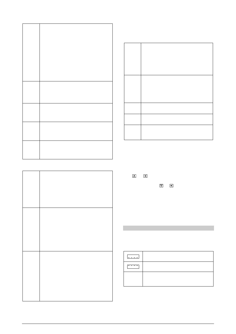
TROUBLESHOOTING
Connection mistakes and configuration errors represent great part of
problems presented in the controller operation. A final review can
avoid waste of time and other damages. Some messages are aimed
at helping the user identify problems.
The sensor temperature reading is below the min.
temperature defined.
The sensor temperature reading is above the max.
temperature defined.
Er 1
Controller fault or Sensor error, examples: Opened
thermocouple, opened, short-circuited or badly
connected Pt100.
If the message “er1” persists after the installation is reviewed,
contact the manufacturer and inform de device serial number.