NOVUS n1500lc User Manual
Page 6
6
6.4 PROCESS VARIABLE RETRANSMISSION
As an option, the indicator can be supplied with an isolated 0-20 mA or 4-20 mA analog output for
Process Variable (PV) retransmission.
The PV values that define the scale of the 0 mA / 4 mA to 20 mA retransmission can be programmed
by the user in the high and low output limits (0v.lol e 0v.kol), at configuration level. High and
low limits can be freely programmed, even with a low limit higher than high limit, resulting in a
reversed retransmission signal (decreasing signal when PV increases).
When this option is available, retransmission will be always active, so that the user will not be required
to turn it on or off.
For a voltage output signal an external shunt (calibrated resistor) should be installed at the analog
output terminals.
6.5 CUSTOMIZED LINEARIZATION
Three types of signals can be user-customized to fit particular linearization profiles. This means that
the operator can configure the instrument to read non-standard crescent non-linear signals with high
accuracy.
7
INSTALLATION
The indicator is designed to be panel mounted. Remove the two plastic fixing clamps from the
instrument, insert the unit into the panel cut-out and slide firmly the fixing clamps from the rear against
the panel.
7.1 RECOMMENDATIONS FOR INSTALLATION
Input signal wires should be laid out away from power lines and preferably inside grounded
conduits.
Instrument mains (line) supply should be suitable for this purpose and should not be shared.
In controlling and monitoring applications, possible consequences of any system failure must be
considered in advance. The internal alarm relay does not warrant total protection.
Use of RC filters (47 R and 100 n, serial) are highly recommended when driving solenoids,
contactor coils or other inductive loads.
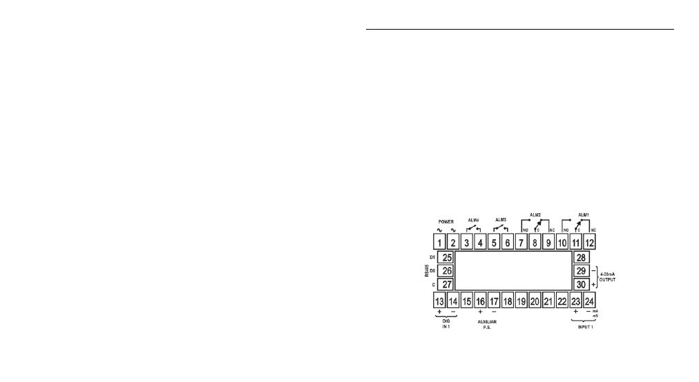
7.2 ELECTRICAL CONNECTIONS
The internal electronics can be removed from the front panel without any cable disassembly. The
input signals and power connections are shown in Figure 2.
Figure 2 – Back Panel Terminals