In.lol, In.kil, Bavd – NOVUS n1500lc User Manual
Page 10: Adres, In.typ, Dp.pos, Scale, Ovt.ty, Ou.lol, Ou.kil
10
Bavd
Communication Baud-Rate – Transmission rate used in the serial
communication of the device (RS-485), in bps. Available rates are: 1200,
2400, 4800, 9600,19200, 38400 and 57600 bps.
Adres
Communication address – Number that identifies the indicator in a network.
9.4 CONFIGURATION CYCLE
In.typ
Input Type - Selects the input signal or sensor type to be connected to the PV
terminals. Refer to Table 1 for options.
Changing the input type causes all other parameters related to PV and alarms
to be changed as well, therefore, this parameter shall be the first to be set.
Dp.pos
Decimal Point Position - Defines the decimal point position in the displayed
value.
Scale
Scale - Defines the indication range.
0
Configurable indication from – 31000 to + 31000.
1
Configurable indication from 0 to + 60000.
2
Configurable indication from 0 to +120000. Only even values will be
displayed (resolution is not improved).
The selected scale affects values of PV, alarm setpoints and Offset.
In.lol
Input Low Limit – Determines the minimum limit for input signals. When the
PV retransmission is used, this value defines the point that will correspond to
the 4 mA (or 0 mA) for any type of programmed input.
In.kil
Input High Limit – Determines the maximum limit for input signals. When the
PV retransmission is used, this value defines the point that will correspond to
the 20mA for any type of programmed input.
Ovt.ty
Analog Output Type - Selects the analog output type to either 0-20 mA or 4-
20 mA.
Ou.lol
Low Limit for Analog Retransmission – Defines the PV value that results in
a 4 mA (or 0 mA) analog output current.
Ou.kil
High Limit for Analog Retransmission – Defines the PV value that results in
a 20 mA analog output current.
Ovt.er
4-20 mA Output behavior in case of failures – Defines the output as 4-20
mA when there is an error in the indication.
Do – Applies a value < 4 mA;
UP – Applies a value > 20 mA
9.5 CUSTOMIZED LINEARIZATION CYCLE
Inp.01
Inp.30
Defines the extreme points (lower and upper) of the customized linearization.
Values must be in the input signal unit.
Ovt.01
Ovt.30
Defines the proportional indications in respect to each segment of the
customized linearization. Values are in the intended indication unit (within the
Indication Lower and Upper Limits).
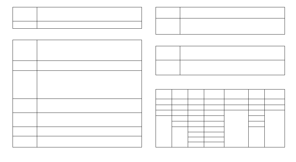
Table 5 shows the sequence of cycles and parameters presented in the indicator display. There are
parameters that must be defined for each alarm available
Work Cycle Alarm cycle
Function
Cycle
Configuration
Cycle
Customized
linearization cycle
Calibration
cycle
Automatic
calibration cycle
8.8.8.8.8.
* Fv.al1
f.fvnc
In.typ
Inp.01 - inp.30
In.lo(
a(all
Al.ref
* Ky.al1
Dig.in
Dp.pos
OVt.01 - ovt.30
In.ki(
a(alk
* Sp.al1
* Bl.al1
Filtr
S(ale
Ov.lo(
* Al.1t1
Ofset
In.lol
Ov.ki(
* Al.1t2
En AZ
In.kil
k.type
AZ ran
OVT.TY
Bavd
0v.lol
Adres
0v.kil
OVT.er
Table 5