3 mechanical installation – NOVUS RHT-P10-485-LCD User Manual
Page 2
RHT-WM-485-LCD, RHT-DM-485-LCD and RHT-P10-485-LCD Transmitters
NOVUS AUTOMATION
2/6
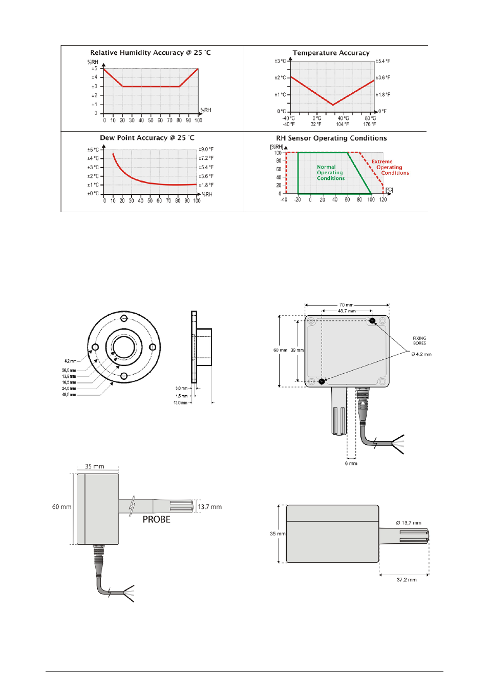
2.1 Measurement Accuracy and Operational Limits of the Sensors:
Figure 3 - Accuracy of humidity and temperature measurement
3 MECHANICAL INSTALLATION
The RHT-DM-485-LCD (Duct Mount) model transmitter must be installed
with a flange. This flange is first screwed onto the duct wall, and the
transmitter probe is then inserted into the flange central hole and locked.
Figure 4 below shows flange dimensions and holes. Available in stainless
steel or polyamide 6.6.
Figure 4 - Flange for fixation of the RHT-DM-485-LCD model
The probe is made in stainless steel, with standard lengths of 150 mm or
250 mm.
Figure 5 – Dimensions of the RHT-DM-485-LCD model
The RHT-WM-485-LCD (Wall Mount) model is designed for wall mounting.
Removing the transmitter cover gives the user access to two bores for fixing
the base, as shown in Figure 6. The transmitter must be fixed with the
sensor capsule directed downwards in order to assure the specific
accuracy and protection level.
Figure 6 - Fixing bores and dimensions of the RHT-WM-485-LCD model
Figure 7 – Dimensions of the RHT-WM-485-LCD model