NOVUS N1040i Indicator User Manual
Page 3
N1040i Indicator
NOVUS AUTOMATION
3/6
RECOMMENDATIONS FOR THE INSTALLATION
• To minimize the pick-up of electrical noise, the low voltage DC
connections and the sensor input wiring should be routed away
from high-current power conductors. If this is impractical, use
shielded cables. In general, keep cable lengths to a minimum.
• The input signals conductors shall be positioned throughout the
factory separate from the output and the power supply
conductors, in grounded conduits if possible.
• The power supply of the electronic instruments shall come from a
proper source for the instrumentation network.
• It is recommended to use RC FILTERS (0.1 uF in series with 100
ohms) to suppress the noise generated by contactors coils,
solenoids, etc.
OPERATION
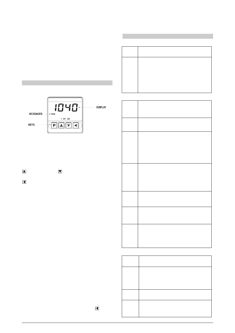
The indicator front panel, together with its elements, can be seen on
Figure 06:
Figure 06 - Identification of the front panel parts
Display: Shows the process variable PV, the configuration
parameters prompts and their respective values/ conditions.
Indicators A1 and A2: signalize the occurrence of an alarm
condition.
Key P: used to walk through the parameters in the menu cycles.
Increment key and
Decrement key: Used to change
parameter values.
Key: A key used to retrocede to the previous displayed
parameter.
START UP
When the controller is powered up, its firmware version is displayed
for 3 seconds, after which the N1540 starts normal operation, when
the value of PV is displayed and the outputs are enabled.
Before the indicator is ready to be used in a given process, it requires
some basic configuration, consisting of assigning values to the
parameters according to the desired behavior. The user shall
understand the importance of each parameter and determine a valid
condition or a valid value for each one of them.
The configuration parameters are grouped in parameters levels
according to their functionalities. The 4 parameters levels are:
1 – Operation
2 – Alarms
3 – Input
4 – Calibration
The “P” key provides the access to the levels and to the parameters
of these levels.
Keeping the P key pressed, at every 2 seconds, the indicator jumps
from one level to another, presenting the first parameter of each
level:
PV >> fva1 >> type >> pass >> PV …
To enter into a particular level, simply release the P key when the
first parameter in that level is displayed.
To walk through the parameters in a level, press the P key with short
strokes. To go back to the previous parameters, use the
Key.
Each parameter symbol is shown on the upper display while its
respective value/condition is shown on the lower display.
Depending on the level of parameter protection adopted, the
parameter PASS precedes the first parameter in the level where the
protection is active. See section PROTECTION CONFIGURATION.
DESCRIPTION OF THE PARAMETERS
OPERATION CYCLE
PV
Indication Display of PV. The value of the measured
variable (PV) is shown on the upper display (red).
Sp.a1
Sp.a2
SetPoint
Alarm
Alarm SP: Value that defines the alarm activation
point. For the alarms set up with the functions of the
type Differential, these parameters define the
maximum differences accepted between PV or a
reference value defined in the parameter ALrF.
For the alarm function ierr, this parameter is not used.
Parameters shown in this level only when enabled in
the parameters sp1.E and sp2.E.
ALARMS CYCLE
Fva1
Fva2
Function
Alarm
Alarm Functions. It defines the functions of the alarms
among the options in Table 02.
al.rf
Alarm
Reference
Reference value used by the alarms with differential
function, minimum differential or maximum
differential.
Sp.a1
Sp.a2
SetPoint
Alarm
Alarm SP: Value that defines the point of activation of
the alarm outputs.
For the alarms programmed with the functions of the
type Differential, these parameters represent the
deviations.
For the ierr alarm function, this parameter has no
meaning.
Sp1.e
sp2.e
SP Enable
It allows the display of the parameters SPA1 and
SPA2 also in the indicator operation cycle.
YES
shows the parameters SPA1/SPA2 in the
operation cycle
NO
DOES NOT show the parameters SPA1/SPA2
in the operation cycle
bla1
bla2
Blocking Alarm
Alarms Initial Blocking.
YES
enables the initial blocking
NO
inhibits the initial blocking
xya1
xya2
Hysteresis of
Alarm
Alarm Hysteresis. It defines the difference between the
value of PV at which the alarm is triggered and the
value at which it is turned off.
flsh
Flash
It allows signalization of an alarm conditions occurrence
by flashing the indication of PV on the indication display.
YES
Enables alarm signalization by flashing PV.
NO
Does not enable alarm signalization by flashing
PV.
INPUT CYCLE
Type
Type
Input Type. Selection of the input type, used by the
indicator. Refer to Table 01.
fltr
Filter
Digital Input Filter – Used to improve the stability of
the measured signal (PV). Adjustable between 0 and
20. At 0 (zero) it means filter turned off and 20 means
maximum filter. The higher the filter value, the slower
is the response of the measured value.
Dp.po
Decimal Point
It determines the position of the decimal point on the
display.
vni t
Unit
It defines the temperature unit to be used:
(
indication in Celsius.
f
indication in Fahrenheit.