Installation / connections, Safety alerts – NOVUS N1040i Indicator User Manual
Page 2
N1040i Indicator
NOVUS AUTOMATION
2/6
The initial blocking is useful, for example, when one of the alarms is
set up as a minimum value alarm, which may cause the activation of
the alarm soon upon the process start-up; an occurrence that may
undesirable in many cases.
The initial blocking is not valid for the function ierr (Sensor Break).
OFFSET
Allows the user to perform fine adjustments to the PV indication. It
allows the correction of measuring errors that appear, for example,
on the replacement of the temperature sensor.
RETRANSMISSION OF PV
The indicator may include an analog output which performs the
retransmission of the values of PV into a signal of 0-20 mA or 4-20
mA. The analog retransmission can be scaled, i.e., there are
minimum and maximum limits to establish the retransmission range,
defined in the parameters “rtLL” and “rtkL”.
The analog output is available on terminals 13 and 14 for models
N1040i-RA and N1040i-RA-485.
In order to obtain retransmission in electrical voltage, the user shall
install a shunt resistor (500 Ω max.) across the analog output
terminals. This resistor value depends on the desired voltage range.
The analog retransmission output is not electrically isolated from the
RS485 serial communication.
24 Vdc AUXILIARY VOLTAGE SOURCE
Another feature that may be available in the indicator is an auxiliary
power supply for exciting field transmitters (two-wire 4-20 mA
transmitters).
The 24 Vdc output is on terminals 13 and 14 for models N1040i-RE
and N1040i-RE-485.
The 24 V auxiliary power supply is not electrically isolated from the
RS485 serial communication.
INSTALLATION / CONNECTIONS
The indicator shall be fastened on a panel, following the sequence of
steps described below:
• Prepare a cut-out of 46 x 46 mm on the panel;
• Remove the mounting clamp from the indicator;
• Insert the indicator into the cut-out from the front side of the
panel;
• Place the clamp on the indicator again, pressing until firm grip to
the panel.
SAFETY ALERTS
The symbols below are used on the equipment and throughout this
manual in order to draw the user´s attention to important information
related to the equipment safety and operation.
CAUTION:
Read the manual thoroughly
before installing and operating
the equipment
CAUTION OR DANGER:
Electrical shock hazard
All safety related instructions that appear in the manual must be
observed to ensure personal safety and to prevent damage to either
the instrument or the system. If the instrument is used in a manner not
specified by the manufacturer, the protection provided by the
equipment may be impaired.
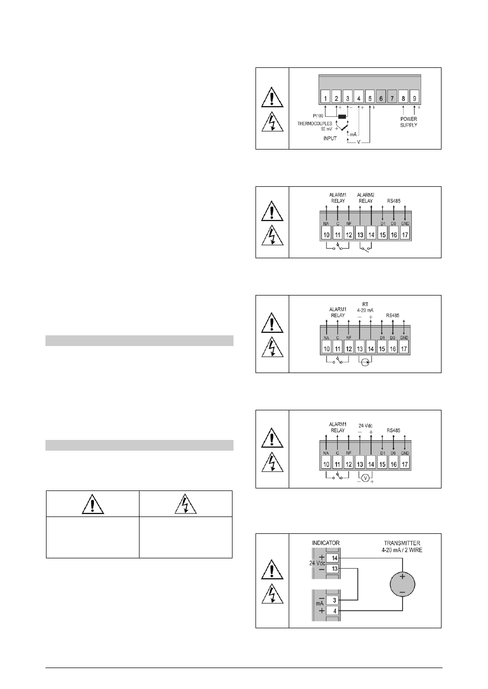
ELECTRICAL CONNECTIONS
The position of the features on the indicator back panel is shown on
Figure 01:
Figure 01 – Inputs connections and power supply
In the models with two alarms and serial communication, the
connections are:
Figure 02 - Alarms and serial communication connections
In the models with one alarm, retransmission of PV and serial
communication, the connections are:
Figure 03 - Alarm, retransmission and serial communication connections
In the models with one alarm, 24 Vdc auxiliary voltage source and
communication, the connections are:
Figure 04 - Alarm, auxiliary source and communication connections
A typical application of the auxiliary voltage source is to supply loop
power for field transmitters (two-wire 4-20 mA). Figure 05 shows the
necessary wiring for this application.
Figure 05 – Example for the use of the indicator auxiliary voltage source