Serial communications, Rs‐485 communications, Modbus rtu communications – Beijer Electronics BFI-P2 V1.21 User Manual
Page 46
User Guide Revision 1.12
www.beijerelectronics.com
46
9. Serial communications
9.1. RS‐485 communications
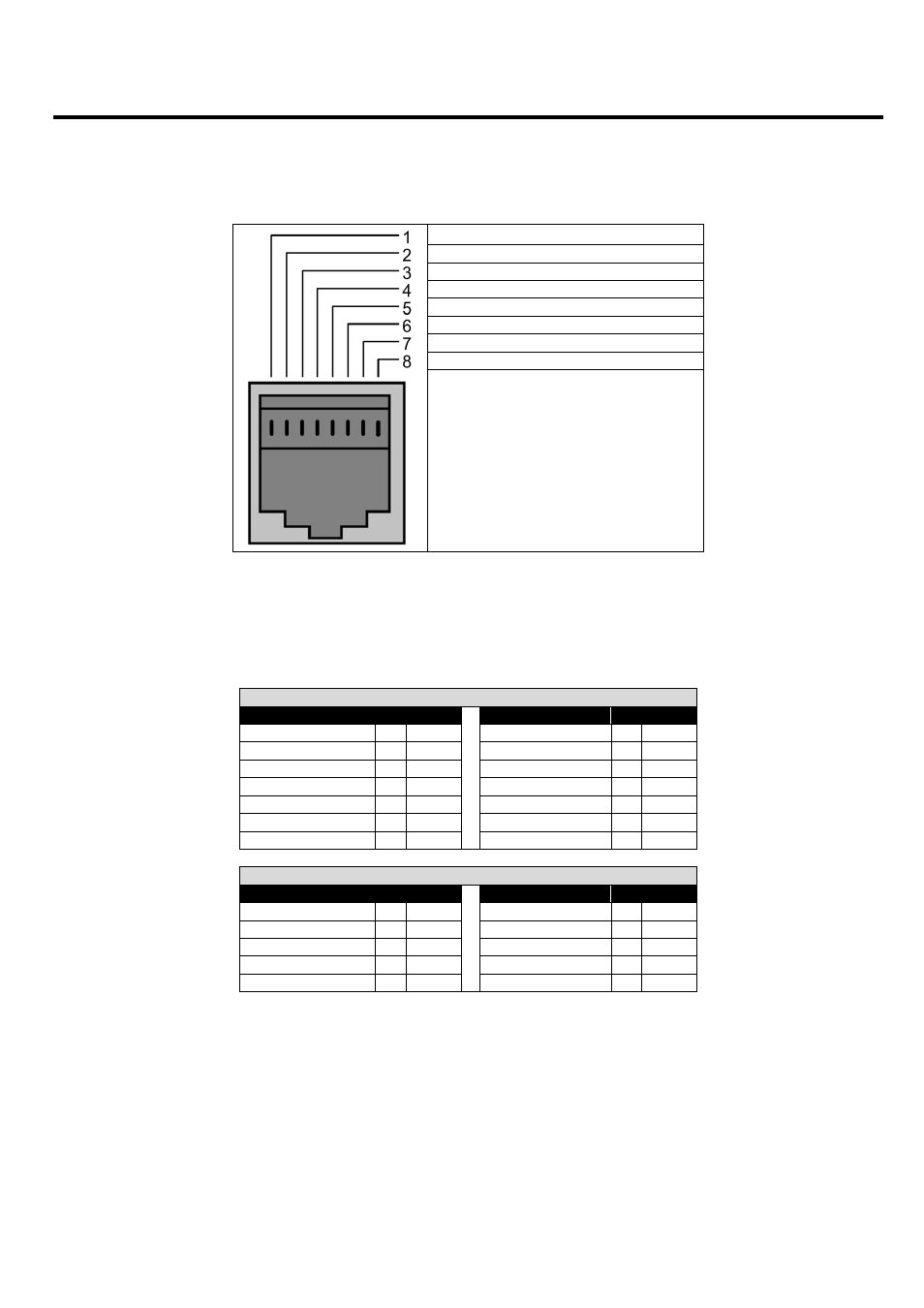
An RJ45 connector located on the drive allows the user to connect the drive to a Modbus RTU network or CANBus via a wired connection.
The electrical signal arrangement of the RJ45 connector is shown as follows:
CAN‐
CAN+
0 Volt
Remote Keypad / PC Connection ‐
Remote Keypad / PC Connection +
+24 Volt Remote Keypad Power Supply
RS 485‐ Modbus RTU
RS 485+ Modbus RTU
9.2. Modbus RTU Communications
9.2.1. Modbus Telegram Structure
The Drive supports Master / Slave Modbus RTU communications, using the 03 Read Holding Registers and 06 Write Single Holding Register
commands. Many Master devices treat the first Register address as Register 0; therefore it may be necessary to convert the Register Numbers
detail in section 9.2.2 subtracting 1 to obtain the correct Register address. The telegram structure is as follows:‐
Command 03 – Read Holding Registers
Master Telegram
Length
Slave Response
Length
Slave Address
1
Byte
Slave Address
1
Byte
Function Code (03)
1
Byte
Function Code (03)
1
Byte
1
st
Register Address
2
Bytes
Byte Count
1
Byte
No. Of Registers
2
Bytes
1
st
Register Value
2
Bytes
CRC Checksum
2
Bytes
2
nd
Register Value
2
Bytes
Etc...
CRC Checksum
2
Bytes
Command 06 – Write Single Holding Register
Master Telegram
Length
Slave Response
Length
Slave Address
1
Byte
Slave Address
1
Byte
Function Code (06)
1
Byte
Function Code (06)
1
Byte
Register Address
2
Bytes
Register Address
2
Bytes
Value
2
Bytes
Register Value
2
Bytes
CRC Checksum
2
Bytes
CRC Checksum
2
Bytes