Beijer Electronics BFI-P2 v1.10 User Manual
Bfi-p2 canopen manual
CANopen USER GUIDE
Beijer Electronics Automation AB
PAGE 1
BFI-P2 CANopen Manual
Author:
Ning Xu
Date:
6
th
February 2012
Revision:
1.10
General:
The CANopen communication profile in the P2 drive is implemented according to the specification DS301
version 4.02 of CAN in automation (
www.can-cia.de
). Specific device profiles such as DS402 are not supported.
Operation Setup:
The CANopen communication function is enabled by default after power up. However in order to use any
control functions through CANopen, user has to set drive parameter P1-12=6.
The CAN communication baud rate can be set by using parameter P5-02. Available baud rates are:
125kbps, 250kbps, 500kbps, 1Mbps. (with default settings as 500kbps)
The Node ID is set up through drive address parameter P5-01 with a default value of 1.
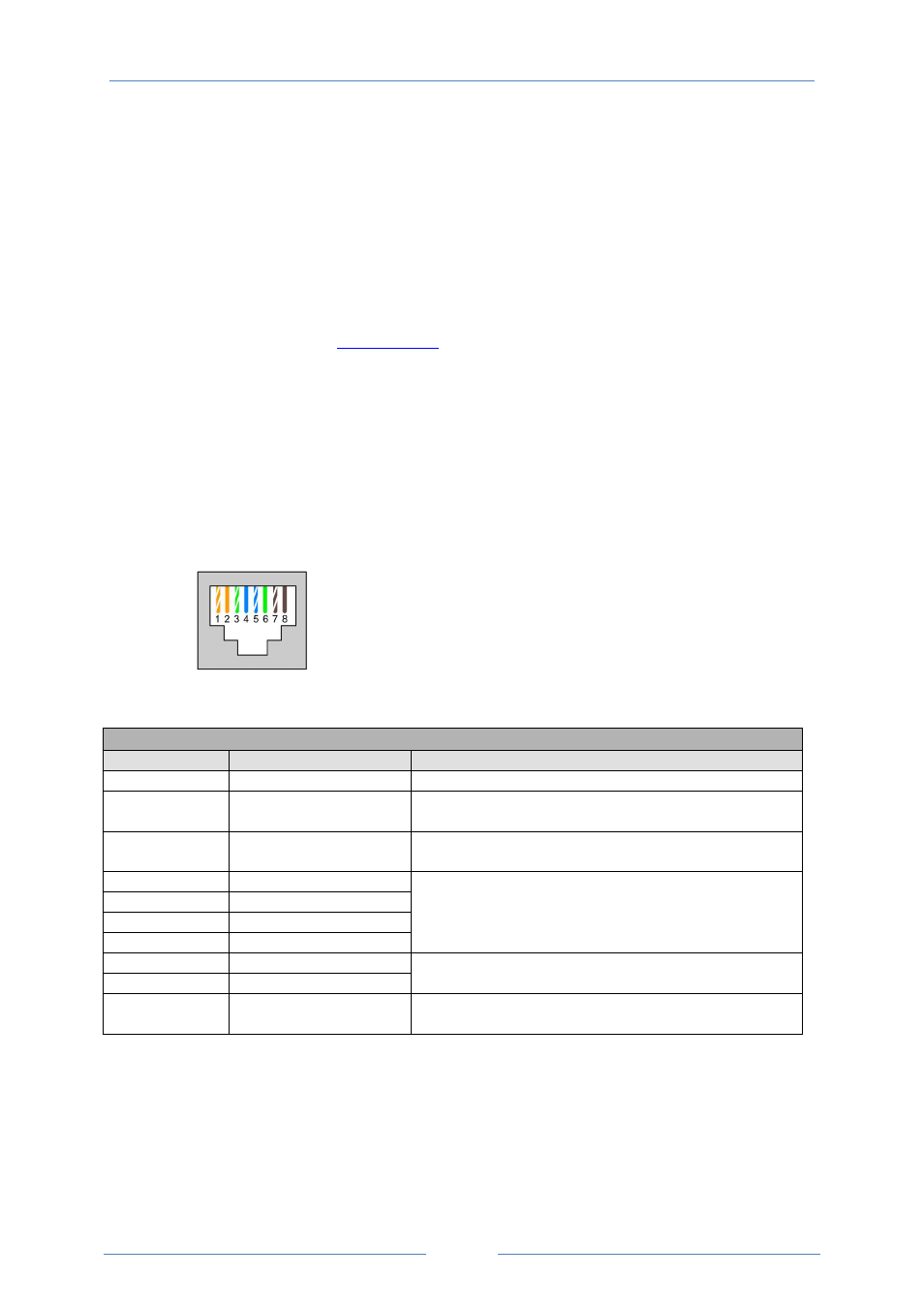
The RJ45 socket is used as CAN signal physical connector with the signals layout as shown blow:
Optidrive P2 provides the following default COB-ID and functions:
Table 1 : Messages and COB-IDs
Type
COB-ID
Function
NMT
000h
Network management
Sync
080h
Synchronous message
COB-ID can be configured to other value.
Emergency
080h + Node address
Emergency message
COB-ID can be configured to other value.
PDO1 (TX)
180h + Node address
PDO1 (RX)
200h + Node address
PDO2 (TX)
280h + Node address
PDO2 (RX)
300h + Node address
Process data object.
PDO1 is pre-mapped and enabled by default.
PDO2 is pre-mapped and disabled by default.
Transmission mode, COB-ID and mapping can be configured.
SDO (TX)
580h + Node address
SDO (RX)
600h + Node address
SDO channel can be used for drive parameter access.
Error Control
700h + Node address
Guarding and Heartbeat function are supported.
COB-ID can be configured to other value.
Note:
1.
The Optidrive P2 SDO channel only supports expedited transmission.
2.
The Optidrive P2 can only support up to 2 Process Data Objects (PDO). All PDOs are pre-mapped, however
PDO2 is disabled by default. Table 2 gives the default PDO mapping information.
3.
Customer configuration (mapping) will
NOT
be saved during power down. This means that the CANopen
configuration will restore to its default condition each time the drive is powered up.
1: CANopen -
2: CANopen +
3: 0V
4: RS485- (Optibus)
5: RS485+ (Optibus)
6: +24V
7: RS485- (Modbus)
8: RS485+ (Modbus)