Control terminal wiring, Connection diagram – Beijer Electronics BFI-P2 V1.21 User Manual
Page 22
User Guide Revision 1.12
www.beijerelectronics.com
22
4.8. Control Terminal Wiring
•
All analog signal cables should be suitably shielded. Twisted pair cables are recommended.
•
Power and Control Signal cables should be routed separately where possible, and must not be routed parallel to each other
•
Signal levels of different voltages e.g. 24 Volt DC and 110 Volt AC, should not be routed in the same cable.
•
Maximum control terminal tightening torque is 0.5Nm
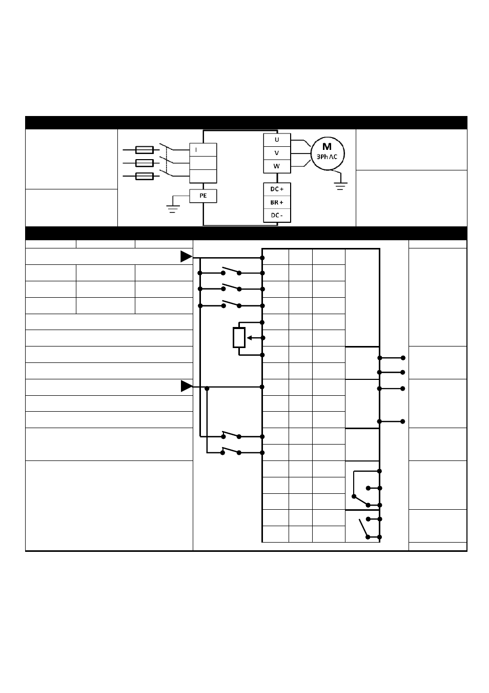
4.9. Connection Diagram
4.9.1. Power Terminal Designations
Incoming Mains Power Supply
For 1 Phase Supply, connect to
L1/L and L2/N terminals.
For 3 Phase Supply, connect to
L1, L2 & L3 terminals.
Phase sequence is not
important.
Motor Connections
Connect the motor to the U, V & W
terminals.
The motor earth must be connected
to the drive
Optional Brake Resistor & DC Bus
Connections
Where a Brake resistor is used, it
must be connected to the BR+ and
DC+ terminals
Protective Earth / Ground
connection.
The drive must be Earthed /
Grounded
4.9.2. Control Terminal Connections& Factory Settings
Open
Closed
+24V Supply (100mA) / External Input
+24V
1
Digital Input 1
Stop
Run (Enable)
DIN1
2
Digital Input 2
Forward Rotation
Reverse Rotation
DIN2
3
Digital Input 3
Analog Speed Ref
Preset Speed
DIN3
4
Digital Inputs : 8 – 30 Volt DC
+ 10 Volt, 10mA Output
+10V
5
Analog Input 1 (Digital input 4)
AIN1
6
0V
7
0V
Output Speed
Analog Output : 0 – 10 Volt / 4‐20mA, 20mA Max
8
AOUT1
0 Volt Supply / External Input
0V
9
0V
Output Current
Analog Input 2 (Digital input 5)
AIN2
10
Analog Output : 0 – 10 Volt / 4‐20mA, 20mA Max
11
AOUT2
External Hardware Enable Cicuit
STO+
12
STO‐
13
Relay Contacts
250VAC / 30VDC
5A Maximum
14
RL1‐C
Default Function :
Healthy
/ Fault
15
RL1‐NO
16
RL1‐NC
17
RL2‐A
Default Function :
Running
18
RL2‐B
L1 / L
L2 / N
L3