Beijer Electronics BFI-P2 V1.21 User Manual
Page 40
User Guide Revision 1.12
www.beijerelectronics.com
40
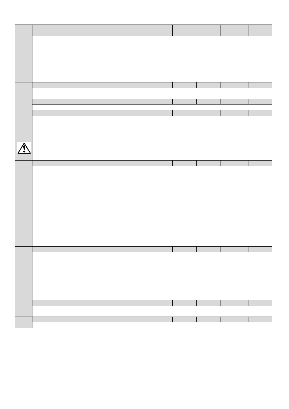
Par
Parameter Name
Minimum
Maximum
Default
P2‐33
Analog Input 2 (Terminal 10) Format
See Below
U 0-10
‐
U 0-10
= 0 to 10 Volt Signal (Uni‐polar)
U 10-0
= 10 to 0 Volt Signal (Uni‐polar)
Ptc-th
= Motor PTC Thermistor Input
A 0-20
= 0 to 20mA Signal
t 4-20
= 4 to 20mA Signal, the Drive will trip and show the fault code
4-20F
if the signal level falls below 3mA
r 4-20
= 4 to 20mA Signal, the Drive will ramp to stop if the signal level falls below 3mA
t 20-4
= 20 to 4mA Signal, the Drive will trip and show the fault code
4-20F
if the signal level falls below 3mA
r 20-4
= 20 to 4mA Signal, the Drive will ramp to stop if the signal level falls below 3mA
P2‐34
Analog Input 2 Scaling
0.0
500.0
100.0
%
Scales the analog input by this factor, e.g. if P2‐30 is set for 0 – 10V, and the scaling factor is set to 200.0%, a 5 volt input will result
in the drive running at maximum speed (P1‐01)
P2‐35
Analog Input 2 Offset
‐500.0
500.0
0.0
%
Sets an offset, as a percentage of the full scale range of the input, which is applied to the analog input signal
P2‐36
Start Mode Select / Automatic Restart
See Below
Auto-0
‐
Defines the behaviour of the drive relating to the enable digital input and also configures the Automatic Restart function.
Edge-r
: Following Power on or reset, the drive will not start if Digital Input 1 remains closed. The Input must be closed after a
power on or reset to start the drive.
Auto-0
: Following a Power On or Reset, the drive will automatically start if Digital Input 1 is closed.
Auto-1
to
Auto-5
: Following a trip, the drive will make up to 5 attempts to restart at 20 second intervals. The drive must be
powered down to reset the counter
.
The numbers of restart attempts are counted, and if the drive fails to start on the final
attempt, the drive will fault with, and will require the user to manually reset the fault.
DANGER! “
Auto"
modes
allow the drive to Auto‐start, therefore the impact on system/Personnel safety needs to be
P2‐37
Keypad Mode Restart Speed
0
3
1
‐
This parameter is only active when P1‐12 = 1 or 2. When settings 0 to 3 are used, the drive must be started by pressing the Start key
on the keypad. When settings 4 – 7 are used, the drive starting is controlled by the enable digital input.
0 : Minimum Speed. Following a stop and restart, the drive will always initially run at the minimum speed P1‐02
1 : Previous Operating Speed. Following a stop and restart, the drive will return to the last keypad setpoint speed used prior to
stopping
2 : Current Running Speed. Where the Drive is configured for multiple speed references (typically Hand / Auto control or Local /
Remote control), when switched to keypad mode by a digital input, the drive will continue to operate at the last operating speed
3 : Preset Speed 8. Following a stop and restart, the Drive will always initially run at Preset Speed 8 (P2‐08)
4 : Minimum Speed (Terminal Enable). Following a stop and restart, the drive will always initially run at the minimum speed P1‐02
5 : Previous Operating Speed (Terminal Enable). Following a stop and restart, the drive will return to the last keypad setpoint speed
used prior to stopping
6 : Current Running Speed (Terminal Enable). Where the Drive is configured for multiple speed references (typically Hand / Auto
control or Local / Remote control), when switched to keypad mode by a digital input, the drive will continue to operate at the last
operating speed
7 : Preset Speed 8 (Terminal Enable). Following a stop and restart, the Drive will always initially run at Preset Speed 8 (P2‐08)
P2‐38
Mains Loss Ride Through / Stop Control
0
2
0
‐
Controls the behaviour of the drive in response to a loss of mains power supply whilst the drive is enabled.
0: Mains Loss Ride Through. The Drive will attempt to continue operating by recovering energy from the load motor. Providing that
the mains loss period is short, and sufficient energy can be recovered before the drive control electronics power off, the drive will
automatically restart on return of mains power
1: Coast To Stop. The Drive will immediately disable the output to the motor, allowing the load to coast or free wheel. When using
this setting with high inertia loads, the Spin Start function (P2‐26) may need to be enabled
2: Fast Ramp To Stop. The drive will ramp to stop at the rate programmed in the 2
nd
deceleration time P2‐25
3: DC Bus Power Supply Mode. This mode is intended to be used when the drive is powered directly via the +DC and –DC Bus
connections.
P2‐39
Parameter Access Lock
0
1
0
‐
0 : Unlocked. All parameters can be accessed and changed
1 : Locked. Parameter values can be displayed, but cannot be changed
P2‐40
Extended Parameter Access Code Definition
0
9999
101
‐
Defines the access code which must be entered in P1‐14 to access parameter groups above Group 1