Pulsafeeder Isochem RGT IOM User Manual
Page 26
21
13. Position the guard (item 36) around the spool (item 29) and insert and tighten the guard screw
(item 37).
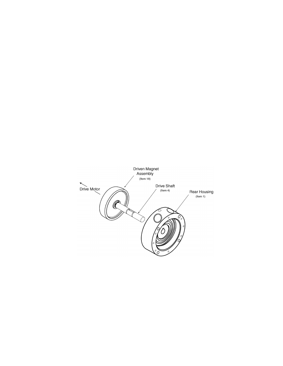
14. Install the Driven Magnet Assembly (item 18) on the drive shaft (item 4).
a) Install the Driven Magnet Assembly inner retaining ring (item 14) by carefully expanding
it over the end of the drive shaft (item 4) and pushing it along the shaft past the front
groove for the outer retaining ring, which will require that the ring be carefully expanded
no more than necessary to pass the groove before arriving and seating fully in the back
groove.
b) Position the Driven Magnet drive key (item 8) in its keyway.
c) Slide the Driven Magnet Assembly (item 18) on the driveshaft (item 4). (The flat side
towards the rear housing.)
d) Install the Driven Magnet outer retaining ring (item 14) by carefully expanding it over the
end of the drive shaft (item 4) and pushing it into the its groove.
Verify that the Magnet Assembly floats freely back and forth between the retaining rings.
This requires that both retaining rings be fully seated in their respective grooves.
15. Insert the Drive Shaft (item 4) with the Driven Magnet Assembly (item 18) attached into the
back of the rear housing (item 1), taking care to avoid damage to the housing bearing (item
9).
Figure 8
16. Install the Impeller (item 6) on the drive shaft (item 4).
a) Install the Impeller inner retaining ring (item 14).
Carefully expand the retaining ring over the end of the drive shaft (item 4) and push it
along the shaft past the front groove for the outer retaining ring, which will require that
the ring be carefully expanded no more than necessary to pass the groove before arriving
and seating fully in the back groove.
b) Position the Impeller drive key (item 8) in its keyway.
c) Slide the Impeller (item 6) on the drive shaft (item 4).