Installation, Save these instructions – Balboa Water Group Aqua-Fan User Manual
Page 2
98704500 Rev. D October 15, 2009
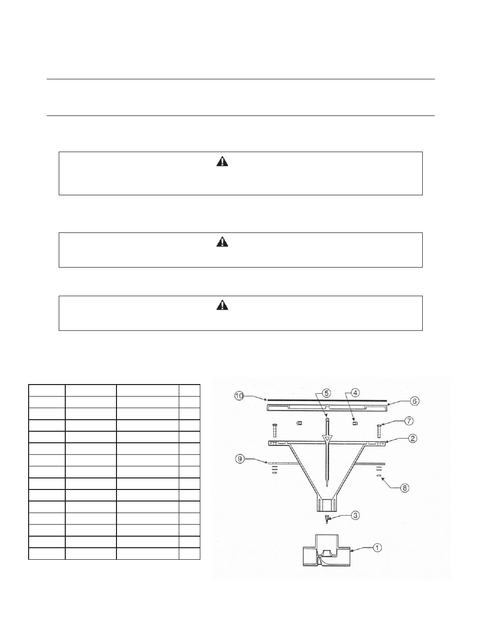
Figure 1
Installation:
a. After locating a suitable flat area on the spa wall, use the provided template to drill 10 holes using a 1/4” size drill, then cut
a rectangular hole (6 1/2” x 1 7/8”).
b: Apply silicone to seal between the jet body (Item No .2) and the spa wall.
NOTE:
Silicone sealant may not be required if gasket (Item No.10) is used. Install gasket to seal between the jet body and the spa wall.
c. Insert the jet body through the rectangular cut, then secure in place by the 10 supplied nuts, using a 3/8” wrench. Torque nut
to 30 in. lb. maximum. Nuts shall be installed in the direction as shown on the exploded view.
CAUTION
This is a PVC to PVC connection. Improper gluing or improper cement selection can cause leaks at glued
connection, which can result in property damage.
CAUTION
This is an ABS to PVC connection. Improper gluing or improper cement usage can cause leaks at the glued
connection which can result in property damage.
CAUTION
Improperly secured lock nuts can result in leaks in the spa wall which could result in property damage.
Torque all lock nuts to the proper specifications called out in these instructions.
Do not substitute alternate lock nuts or mounting hardware.
d. Orient the tee (Item No.1) to the suitable plumbing direction, then attach to jet body using plastic pipe cement Weld-On
No. 793 (ABS to PVC) or equivalent.
e. Using Weld-On No. 710 (PVC), or equivalent, secure the jet air/water inlet ports (as marked) to the spa plumbing system.
Item No. Part Number Description
Qty.
1
46033900 Tee
1
2
980100 Body
1
3
46033000 Boot
1
4
46032000 Hinge
2
5
46031000 Flapper
1
6
980200 Cover
1
7
98211900 Screw
10-24 10
8
41475000 Nut
10-24
10
9
46035700 Gasket
(opt.) 1
10
Deco Ring (opt.)
1
46912500 Polished
SS
46912600 Polished
Brass
46912700 Antique
Brass
98719600 Template
1
Parts List (See Figure No. 1)
SAVE THESE INSTRUCTIONS