Start up exh 1 p2 exh 1 p2 a b c c – Karcher HKF 200 K2 User Manual
Page 33
-
13
Prior to the initial startup, the supply lines
from the site-supplied supply units must be
connected to the tank cleaning device.
Caution
In order to avoid damage to the com-
pressed air drive by condensation wear
and lack of lubrication, install a mainte-
nance unit into the compressed air supply.
This maintenance unit must be laid out as
follows:
–
Air throughput of 60 m
3
/h (with standard
conditions)
–
Pressures of up to 0.6 MPa (for safety
reasons)
–
The hose line between the mainte-
nance units and the tank cleaning de-
vice must not be longer than 3 m.
The maintenance unit consists of:
–
Filter
–
Water separator
–
Pressure regulator with manometer
–
Proportional oiler
Fill the proportional oiler with a suitable
lubricant. Oil type - see operating in-
structions of the compressed air motor.
Set the oiler to 50 mm
3
oil per standard
cubic meter (mm
3
/m
3
) compressed air,
see operating instructions of the com-
pressed air motor.
–
Hose size for supply air as per DIN 10
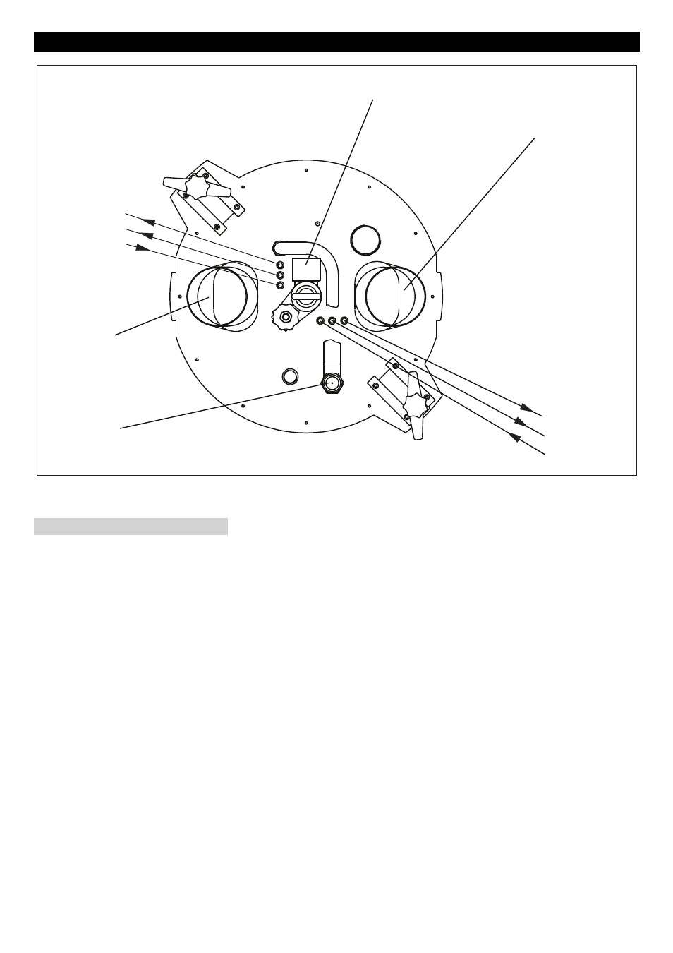
Blow the hose clean and connect it to
the compressed air connections (P2).
The exhaust air of the compressed air mo-
tors exits at the connections "1" and "EXH".
Here, you can connect mufflers or exhaust
hoses.
Note: A reflux of the exhaust air causes an
unsafe run of the compressed air motor.
Therefore, you must use large enough muf-
flers or hoses.
Start up
EXH
1
P2
EXH
1
P2
a
b
c
c
Compressed air connection
Maintenance unit
Connect supply air hose
Exhaust air
33
EN