Specifications, Wiring, Wiegand reader output – HID Wiegand PINPad Rev D Installation Guide User Manual
Page 2
PINpad 26-bit Wiegand Reader, 7393800, rev D
Specifications
Base Part
Number
Input
Voltage
Current
Operating
Temperature
Cable Distance
310
5 – 12 VDC
40mA
(typical)
-31°F to + 149°F
(-35°C to + 65°C)
Maximum cable distance is
100 feet (30.5 m) using six
conductor, shielded 18 AWG
cable.
For distances greater than
100 feet the unit should be
powered locally and a Line
Extender used to transmit the
data up to 5,000 feet
(1524 m).
Wiring
For maximum performance the Wiegand PINpad should be connected to the host panel
with a six-conductor, shielded, 18 AWG cable.
The tan wire (Case Ground) should be connected to an earth ground as close to the
Wiegand PINpad as possible.
Wire Color
Description
Red
+5 to 12 VDC, 120 mA Typical, 150 mA Max.
Black DC
Ground
Green
Data 0. Transmits the Binary “0”s of a Wiegand Data Stream (See Wiegand
Reader Output)
White
Data 1. Transmits the Binary “1”s of a Wiegand Data Stream (See Wiegand
Reader Output)
Brown
LED Control. High = Red on/Green off. Low = Red off/Green on.
Blue
Hold Line. High = Inactive. Low = Stores up to 64 bits of card data.
Tan
Case Ground. Connect to “Earth Ground” as close to the PINpad as possible.
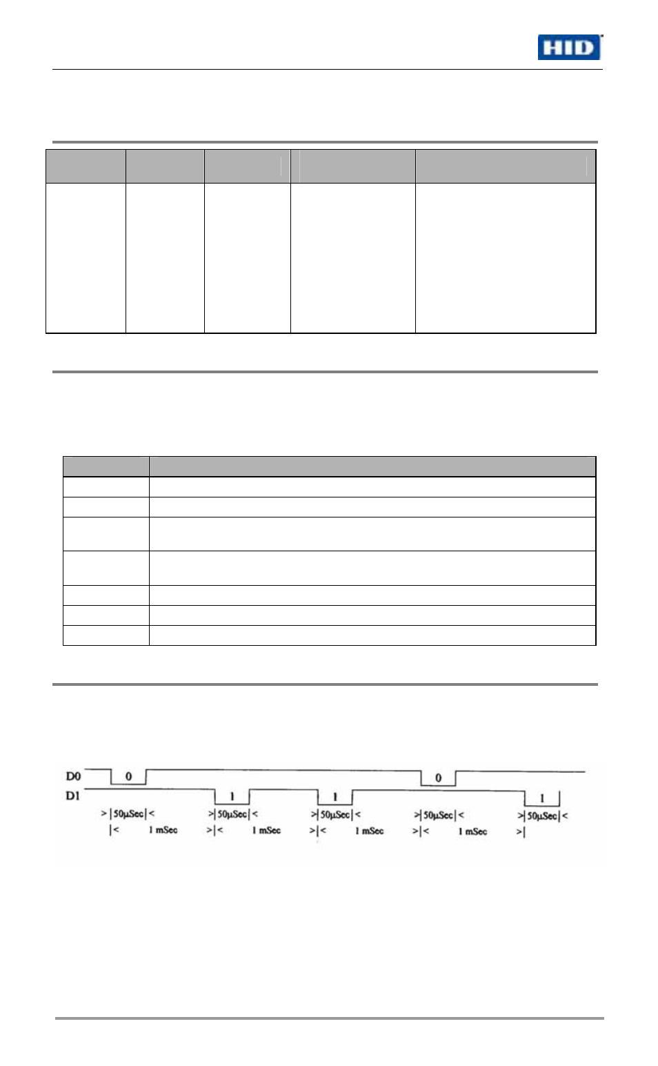
Wiegand Reader Output
Wiegand readers convert the binary codes embedded within a Wiegand card into
electronic data, see Figure 1. The direction in which a card is passed through the reader
will affect the order in which the data is sent from the reader. Bits are recognized as a line
transitioning low (below 1.1 volts) for 50 µSec.
Figure 1 Binary Stream “01101” Wiegand Output
Page 2 of 6
© 2007 HID Global Corporation. All rights reserved.
October 19, 2007