Pivclass, Wiring, Attention – HID pivClass Installation Guide User Manual
Page 4: Terminal reader pigtail reader
INSTALLATION GUIDE
4
© 2012 - 2014 HID Global Corporation/ASSA ABLOY AB. All rights reserved.
PLT-01134 A.2
pivCLASS
R10-H, RP10-H, R15-H, RP15-H, R30-H, RP30-H, R40-H, RP40-H, RK40-H,
RPK40-H, RKCL40-P, RPKCL40-P, RKCLB40-P, RPKCLB40-P
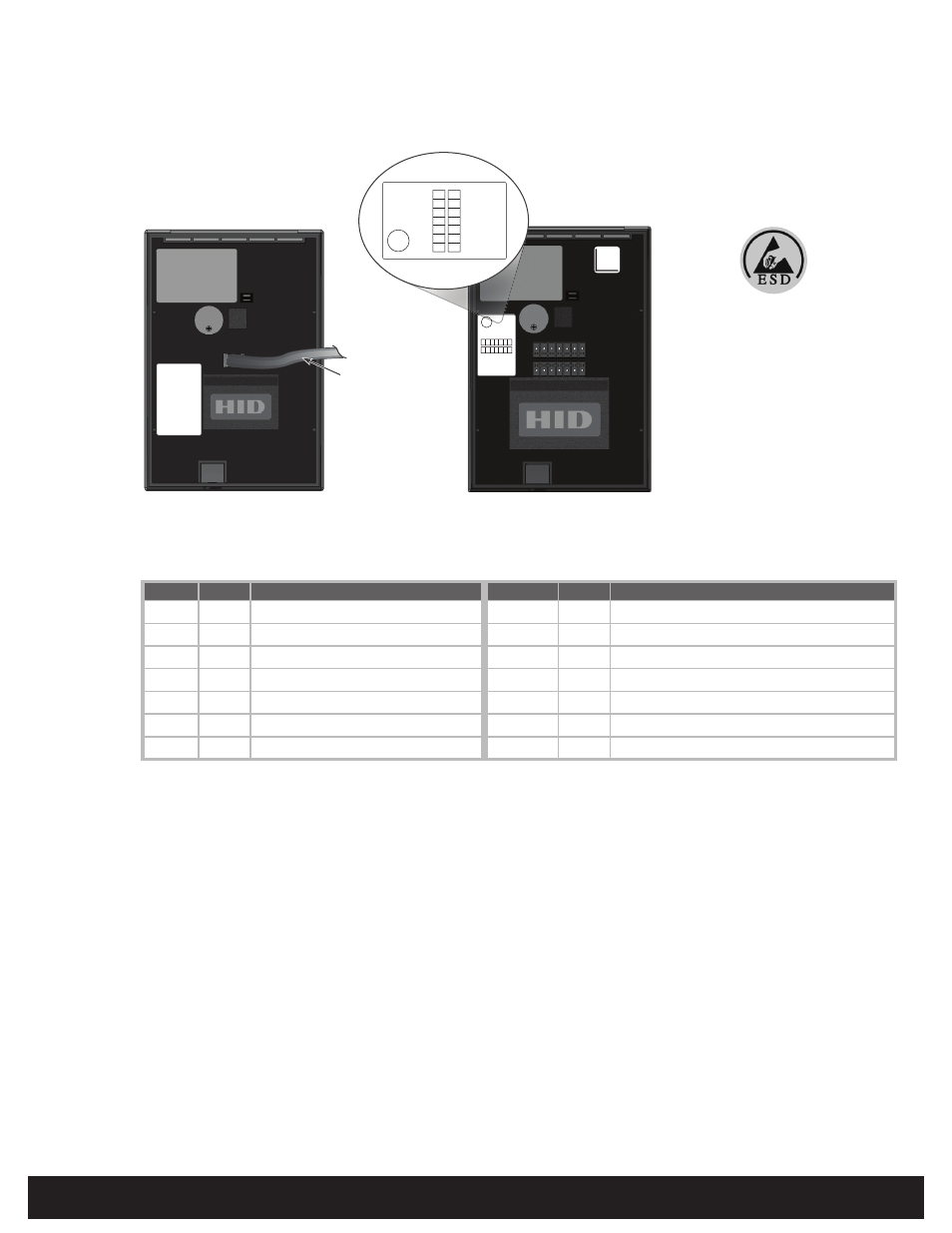
Wiring
2
ATTENTION
Observe precautions for handling
ELECTROSTATIC SENSITIVE DEVICES
Pigtail
Terminal Description
Pigtail
Terminal
Description
Yellow
P1-1
Beeper Input
Red / Green
P2-7
GPIO1 (RS232-T / RS485-FDX/HDX-A)
See Note 1
Orange
P1-2
LED Input (GRN)
Tan
P2-6
GPIO2 (RS232-R / RS485-FDX/HDX-B)
See Note 1
Black
P1-3
Ground (RTN)
Violet
P2-5
Open Collector Output / Tamper
See Note 2
Red
P1-4
+VDC
White
P2-4
Wiegand Data 1 / Clock
See Note 3
Drain
P1-5
Unused
Green
P2-3
Wiegand Data 0 / Data
See Note 3
Brown
P1-6
LED Input (RED)
Pink
P2-2
GPIO3 (RS485-FDX-Z)
See Note 1
Blue
P1-7
Hold Input
Gray
P2-1
GPIO4 (RS485-FDX-Y)
See Note 1
Notes
1
RS-485 applicable for pivCLASS readers.
2
Tamper Output - When activated, output synchronizes to ground (default).
3
Dependent upon reader configuration. See the HTOG for Wiegand and Clock-in-Data configurations.
P1
P2
Beeper
GRN LE
D
GN
D
+VDC
DRAIN
RE
D
HOLD
GPIO
1
GP10
2
OC/TMP
R
DATA
1/CL
K
DATA
2/D
ATA
GPIO
3
GPIO
4
Beeper
GRN LED
GND
+VDC
DRAIN
RED
HOLD
GPIO1
GP102
OC/TMPR
DATA1/CLK
DATA2/DATA
GPIO3
GPIO4
Terminal Reader
Pigtail Reader
18 in
(0.46 m)
BEEP (YEL)
GRN LED (ORN)
GND (BLK)
+VDC (RED)
DRAIN (BARE)
RED LED (BRN)
HOLD (BLU)
GPIO1(RED/GRN)
GPIO2 (TAN)
OC/TMPR (VIO)
DATA1 (WHT)
DATA2 (GRN)
GPIO3 (PINK)
GPIO4 (GRAY)
(Terminal block and module
position varies)
(Module position varies)
Note: Previous iCLASS readers had
reversed RS-485 wiring ( P2-7 &
P2-6 - A & B). When upgrading to
a pivCLASS reader, ensure proper
connections as defined below.