Pivclass, Parts list specifications, Pivclass protocol – HID pivClass Installation Guide User Manual
Page 2: Wiegand and osdp protocol
INSTALLATION GUIDE
2
© 2012 - 2014 HID Global Corporation/ASSA ABLOY AB. All rights reserved.
PLT-01134 A.2
pivCLASS
R10-H, RP10-H, R15-H, RP15-H, R30-H, RP30-H, R40-H, RP40-H, RK40-H,
RPK40-H, RKCL40-P, RPKCL40-P, RKCLB40-P, RPKCLB40-P
Parts List
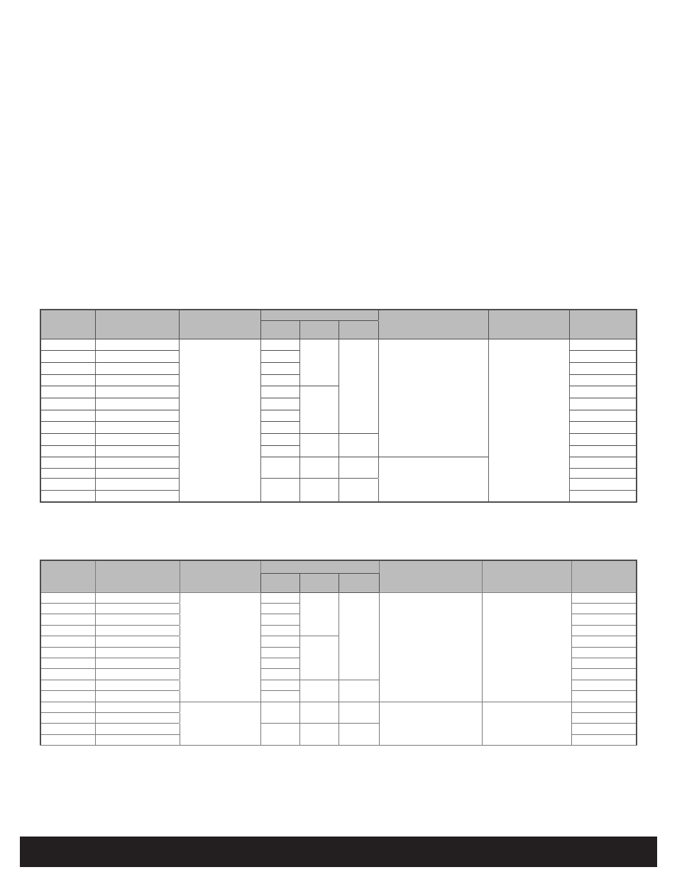
Specifications
pivCLASS Protocol
UL Reference Number Deciphering
x
1
Reader Colors:
K = Black, G = Gray
x
2
Wiring:
N = Pigtail,
T = Terminal
x
3
Communications: N = No Module,
R = RS-485 (OSDP)
1 - Reader and base plate assembly
1 - Installation guide
2 - Terminal connector - terminal readers only
RKCL40, RPKCL40, RKCLB40, and RPKCLB40
4 - M3.5 mm x 12 mm phillips machine screw
4 - #6-32 x .375” phillips self-tapping machine screw
4 - #6 x 1.5” phillips sheet metal screw
3 - #6-32 x .4375” spanner security screw, anti-tamper (Black)
3 - #6-32 x .4375 phillips security screw (Black)
1 - Mounting Gasket
R10, RP10, R15, RP15, R30, RP30, R40, RK40, RP40, and RPK40
2 - M3.5 mm x 12 mm phillips machine screw
3 - #6-32 x .375” phillips self-tapping machine screw
2 - #6 x 1.5” phillips sheet metal screw
1 - #6-32 x .375” spanner security screw, anti-tamper
1 - Mounting gasket - (Optional)
Recommended
• Cable, 6 conductor, 22 or 24 AWG [65 mm or 51 mm]
(Belden 3108A or equivalent) - RS-485 + power
• Cable, 6 to 9 conductor, 22 or 24 AWG [65 mm or 51 mm]
(Alpha 1296C or equivalent) - Wiegand + power
• DC power supply
• Metal or plastic double-gang junction box -
RPKCL40 / RPKCL40 /
RKCLB40 / RPKCLB40
• Metal or plastic single-gang junction box -
R10 / RP10 / R15 / RP15 / R30 /
RP30 / R40 / RP40 / RK40 / RPK40
• Reader spacer when using metal junction boxes - see HID HTOG.
• Security tool (for spanner security screw, anti-tamper) HID 04-0001-03
PRODUCT
BASE PART NUMBER
INPUT VOLTAGE (VDC)
CURRENT
OPERATING TEMPERATURE
CABLE LENGTH
UL REF NUMBER
Standby
AVG
1
Maximum
AVG
2
PEAK
3
R10-H
900NHR
12VDC
60mA
100mA
200mA
-30° to 150° F
(-35° to 65° C)
RS-485 = 500 ft - 22 AWG
(152 m)
300 ft - 24 AWG
(91 m)
R10E
x
1
x
2
x
3
RP10-H
900PHR
75mA
RP10E
x
1
x
2
x
3
R15-H
910NHR
60mA
R15E
x
1
x
2
x
3
RP15-H
910PHR
75mA
RP15E
x
1
x
2
x
3
R30-H
930PHR
65mA
110mA
R30E
x
1
x
2
x
3
RP30-H
930PHR
85mA
RP30E
x
1
x
2
x
3
R40-H
920NHR
65mA
R40E
x
1
x
2
x
3
RP40-H
920PHR
85mA
RP40E
x
1
x
2
x
3
RK40-H
921NHR
85mA
125mA
220mA
RK40E
x
1
x
2
x
3
RPK40-H
921PHR
95mA
RPK40E
x
1
x
2
x
3
RKCL40-P
923NPR
150mA
185mA
250mA
-4° to 149° F
(-20° to 65° C)
RKCL40E
x
1
x
2
x
3
RPKCL40-P
923PPR
RPKCL40E
x
1
x
2
x
3
RKCLB40-P
924NPR
165mA
215mA
275mA
RKCLB40E
x
1
x
2
x
3
RPKCLB40-P
924PPR
RPKCLB40E
x
1
x
2
x
3
PRODUCT
BASE PART NUMBER
INPUT VOLTAGE (VDC)
CURRENT
1
OPERATING TEMPERATURE
CABLE LENGTH
5
UL REF NUMBER
Standby
AVG
2
Maximum
AVG
3
PEAK
4
R10-H
900N
5-16VDC
12VDC for RS-485
60mA
100mA
200mA
-30° to 150° F
(-35° to 65° C)
Communication Lines
Wiegand = 500 ft - 22 AWG
(152 m)
300 ft - 24 AWG
(91 m)
RS-485 = 4000 ft - 24 AWG
(1,219 m)
R10E
x
1
x
2
x
3
RP10-H
900P
75mA
RP10E
x
1
x
2
x
3
R15-H
910N
60mA
R15E
x
1
x
2
x
3
RP15-H
910P
75mA
RP15E
x
1
x
2
x
3
R30-H
930N
65mA
110mA
R30E
x
1
x
2
x
3
RP30-H
930P
85mA
RP30E
x
1
x
2
x
3
R40-H
920N
65mA
R40E
x
1
x
2
x
3
RP40-H
920P
85mA
RP40E
x
1
x
2
x
3
RK40-H
921N
85mA
125mA
220mA
RK40E
x
1
x
2
x
3
RPK40-H
921P
95mA
RPK40E
x
1
x
2
x
3
RKCL40-P
923N
12VDC
150mA
185mA
250mA
-4° to 149° F
(-20° to 65° C)
Wiegand and RS-485
500 ft - 22 AWG (152 m)
300 ft - 24 AWG (91 m)
RKCL40E
x
1
x
2
x
3
RPKCL40-P
923P
RPKCL40E
x
1
x
2
x
3
RKCLB40-P
924N
165mA
215mA
275mA
RKCLB40E
x
1
x
2
x
3
RPKCLB40-P
924P
RPKCLB40E
x
1
x
2
x
3
Wiegand and OSDP Protocol
1
Standby AVG - RMS current draw without a card in the RF field.
2
Maximum AVG - RMS current draw during continuous PIV card reads. Not evaluated by UL.
3
Peak - highest instantaneous current draw during RF communication.
UL Reference Number Deciphering
x
1
Reader Colors:
K = Black, G = Gray
x
2
Wiring:
N = Pigtail,
T = Terminal
x
3
Communications: N = No Module, R = RS-485
1
Communication protocols other than Wiegand or Clock
& Data require an additional hardware module which
increases current by 30 mA.
2
Standby AVG - RMS current draw without a card in the RF field.
3
Maximum AVG - RMS current draw during continuous PIV card reads. Not
evaluated by UL.
4
Peak - highest instantaneous current draw during RF communication.
5
Wiegand Cable Lengths:
100 ft (30.5 m) 22 AWG @ 5 - 6.4VDC
500 ft (152 m) 22 AWG @ 6.5 - 16VDC