1 wiring, 1 internal optical tamper disable jumpers, 2 relay jumpers – HID EDGE EVO EWM-M Wiegand Module Installation Guide User Manual
Page 2: Door / reader module, Wiring
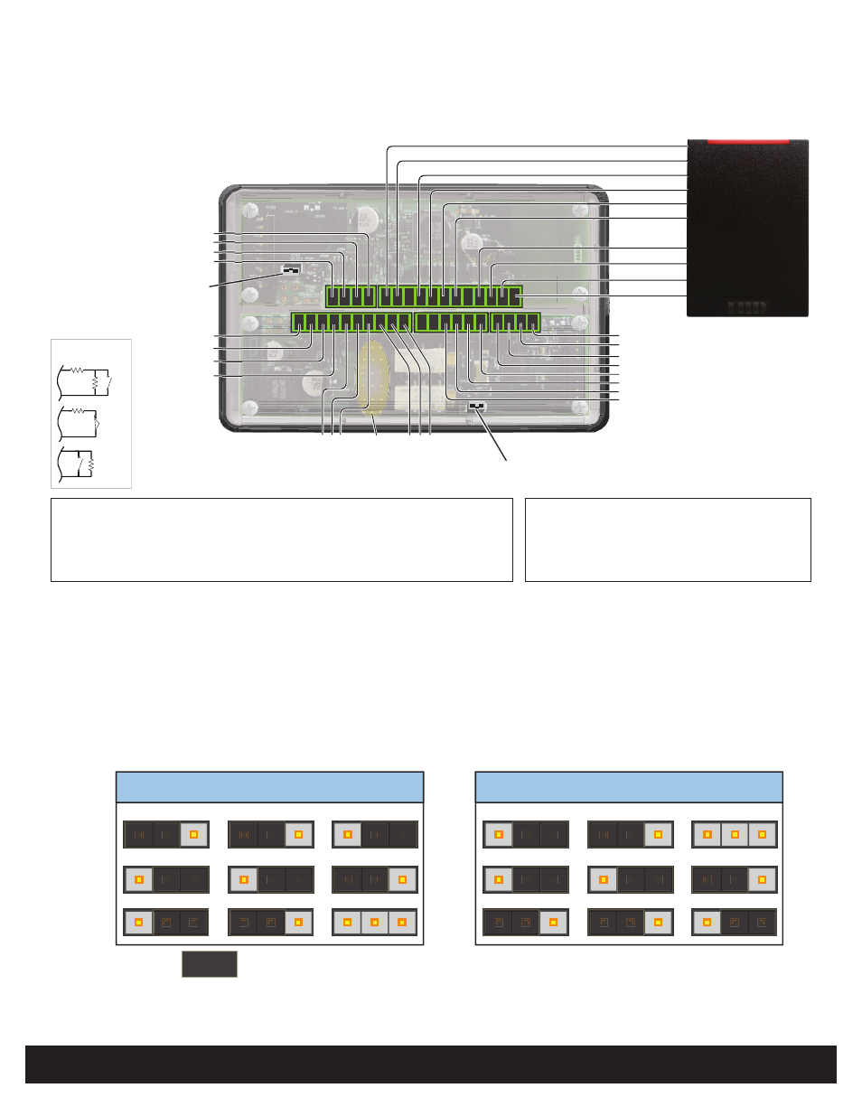
Door / Reader Module
EDWM-M
82363-901 C.1
INSTALLATION GUIDE
2
©2009 - 2012 HID Global Corporation. All rights reserved.
1
Wiring
GND
CAN_H
CAN_L
(12 VDC or 24 VDC) CAN V+
Reader PWR
GND
Data0 / DATA
Data1 / CLK
GRN LED
RED LED
Hold
Beep
Reader Tamp+
Hi-O Group Select Jumper
Short = Group 1, Open = Group 2
Outside Door
Inside Door
( )
P7
P4
P6
P8
P5
P9
Relay
Jumpers
Reader Tamp -
Hi-O Group Select Jumper
Short = Group 1, Open = Group 2
Outside Door Inside Door
( )
NO
NC
CO
M
CAN V+
GND
CAN_H
CAN_L
1
P1 4 1
P10
6 1
P3
10
DS
NO
NC
CO
M
AUX
+
- AC Fail Input Sense
+
- BATT Fail Input Sense
+
- REX
+
-
Door
Mon
*
*
= Internal Tamper Disable Jumpers
*
12
P2
1
4
P1 1
*
*
HI-O CANbus
1.1
Internal Optical Tamper Disable Jumpers
To disable the internal optical tamper sensor for the right side PCB (Door interface board), attach a jumper wire from P3 pin 1 to
P3 pin 2.
To disable the internal optical tamper sensor for the left side PCB (Reader interface board), attach a jumper wire from P2 pin 10
to P2 pin 5.
CAUTION: The unit ships from the factory with the Door interface board jumper pre-installed on the connector.
Removing this jumper causes false tampers to trigger.
Note:
If desiring an external tamper, wire an unsupervised Normally Closed contact, replacing the pre-installed jumper.
1.2
Relay Jumpers
AUX Wet
CAN V+
AUX Wet
+12VDC
AUX Dry
DS Wet
CAN V+
DS Wet
+12VDC
DS Dry
3
1
P9
P5
P8
3
1
3
1
3
1
P6
P4
P7
3
1
3
1
JUMPER =
Optional
Supervised Inputs
1-6K
N/O
1-6K
N/C
1-6K
1-6K
N/O
Notes:
Connect the Door Monitor to avoid a Door Forced
Alarm.
Use Ground (GND) for the drain or tie the drain to the
reader ground if the reader is not powered off of the
module (5 VDC reader).
CAUTION: Some magnetic locks exhibit both high inrush current when activated and a
high instantaneous break voltage when de-energized due to magnetic field collapse. It
is recommended you use of a snubber circuit across the controlling relay terminals to
protect the controlling relay contacts. Go to support.hidglobal.com, see Solution 891 -
How do I wire a High In-Rush Current locking device to VertX/EDGE EVO.
Not evaluated by UL.