ROTHENBERGER Modul ROLOC PLUS User Manual
Page 20
ENGLISH
18
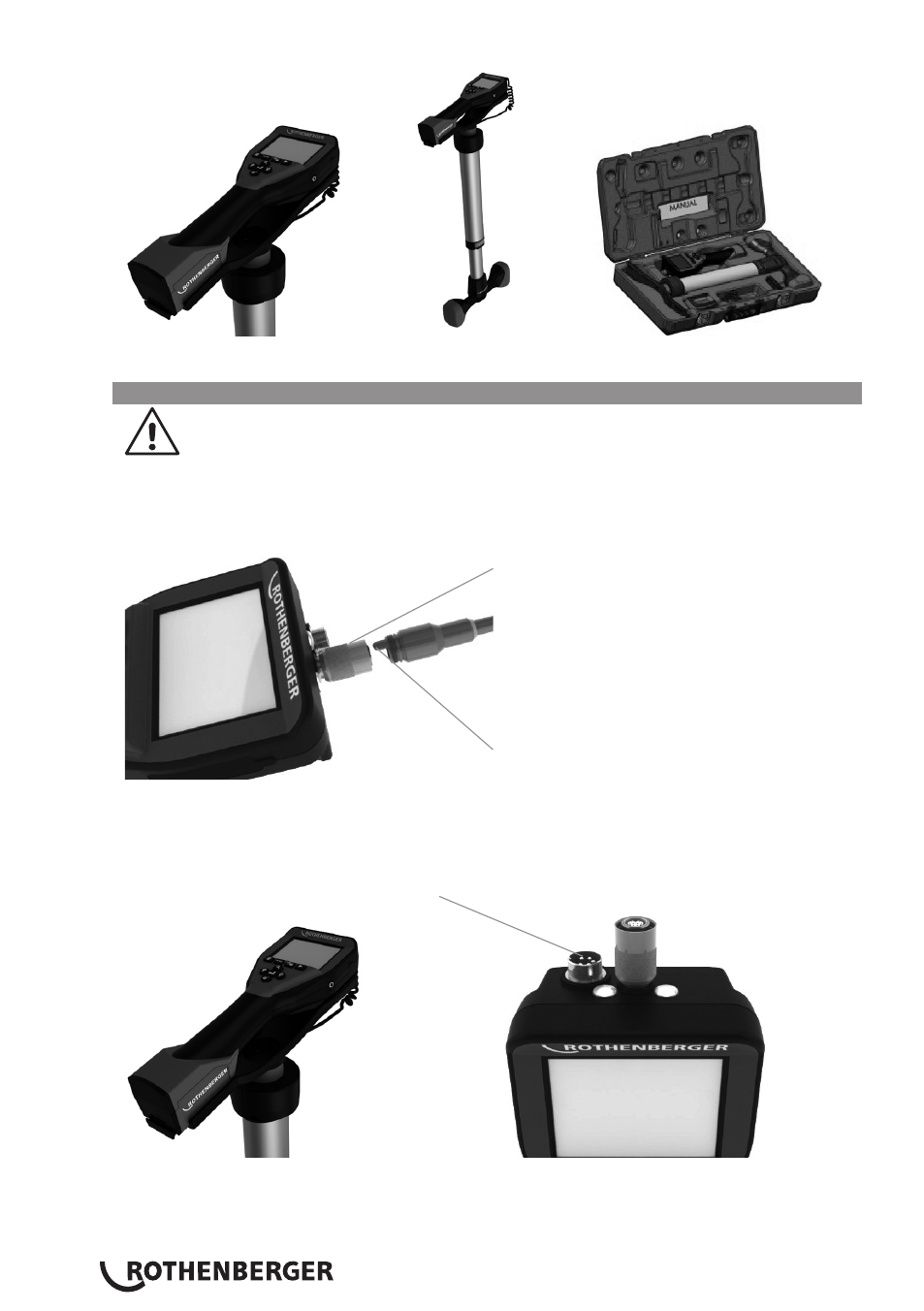
Figure 1 – ROLOC PLUS (No. 1500000057) System Components
3.3
Installing ROSCOPE 1000/i2000 Imager / Module ROLOC PLUS
Only one device should be connected to the unit at a time. Always make sure the unit is
off when installing or removing imagers or other accessories.
To use the ROSCOPE 1000/i2000 inspection device, the 17mm imager or the Module ROLOC
PLUS must be connected to the handheld device. To secure connector to the handheld device,
make sure the key and slot (Figure 2 and 3) are properly aligned. Once they are aligned, hand-
tighten the knurled nut to hold the connection in place.
Slot
Key
Figure 2 - Cable Connections (Connector Style A, Black Color)
NOTE: Connector is the same for either ROSCOPE 1000/i2000 imager (or) Module ROLOC PLUS.
Slot for Connector Style B
Figure 3 – Cable Connections (Connector Style B, Silver Color)
NOTE: Connector Style B is used to attach previous versions of the ROSCOPE Imager Cable.
- RODIACUT 130 PRO (124 pages)
- RODIACUT 131 DWS (130 pages)
- RODIACUT 170 PRO C/170 PRO D (144 pages)
- RODIACUT 400 PRO D (144 pages)
- Schnellspannsäule (24 pages)
- COLLINS CLASSIC 22 A (104 pages)
- COLLINS RHINO 4 (112 pages)
- Präzisions-Gewindeschneidköpfe Automatik Schneidköpfe (28 pages)
- Präzisions-Gewindeschneidköpfe ROTHENBERGER Standard Schneidköpfe (32 pages)
- Pressbacken Compact (44 pages)
- Pressschlingen Standard (24 pages)
- RE 17 Dreigas-Anlage AMS 10/10 (80 pages)
- ROFLARE REVOLVER (20 pages)
- ROGROOVER 2 - 12 (92 pages)
- ROMAX AC ECO (88 pages)
- ROMAX Compact (132 pages)
- ROPOWER 50 R (232 pages)
- ROTHERM 2000 Weichlöt-Gerät (66 pages)
- ROXY 400 L Set (132 pages)
- Sicherheitsfußschalter (84 pages)
- SUPERTRONIC 2 SE/3 SE/4 SE (284 pages)
- Taumel-Bördelgerät (2 pages)
- Wechselpressbacken Compact (44 pages)
- ROFROST ECO (104 pages)
- ROFROST TURBO 1.1/4 und 2 (108 pages)
- Modul Pipe 25/16 (256 pages)
- Modul ROSCAN 150 (236 pages)
- ROCAM 3 Multimedia (360 pages)
- ROCAM 3 Multimedia Softwareinstallation (56 pages)
- ROCAM Plus (116 pages)
- ROSCOPE i2000 (308 pages)
- ROSCOPE 1000 Set TEC 1000 (96 pages)
- ROSCOPE i2000 Wifi-Connection (12 pages)
- Hochdruck-Rohrreiniger (76 pages)
- R 100 SP (52 pages)
- R 140 B (32 pages)
- R 550 (180 pages)
- ROCAL 20/ROMATIC 20 (36 pages)
- ROCLEAN Injektor (44 pages)
- ROJET 30/130 (52 pages)
- ROPULS Spülkompressor (100 pages)
- ROSPEED 3F (108 pages)
- ROCUT XL (32 pages)
- ROCUT UKS 160/355 (96 pages)