Alliance Laundry Systems UW35AV User Manual
Page 33
© Copyright, Alliance Laundry Systems LLC – DO NOT COPY or TRANSMIT
Specifications and Dimensions
31
F232228
Connecting External Liquid Supplies to
the Washer-Extractor
1. Remove knockout from supply dispenser. Refer
to Figure 19. Plugs are assembled inside the
tubing ring.
2. Install PG connector in hole with strain reliefs,
included in the seal nut.
3. Insert tubes through base. Do not remove cups.
Tube should extend into the plastic cup, with the
exception of the softener tube, which should be
routed to the outside of the cup.
4. Tighten the seal nut to prevent tubing from
escaping the assembly.
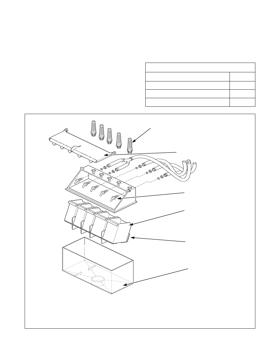
The UW35AV – UW125AV have a polypropylene
supply dispenser. Refer to Figure 20.
Do not attempt to make chemical injection electrical
connections to points other than those provided
specifically for that purpose by the factory.
Figure 20
Chemical Injection Supply System
Specifications
AV
Number of dry supply compartments
5
Number of liquid supply connections
5
Liquid supply connection size, in (mm)
.5 (12.7)
PHM553N
1
Strain Relief for Liquid Chemical Supply Lines
4
Dry Supply Cups
2
Supply Dispenser Lid
5
Dry Supply Insert
3
Nozzles
6
Polypropylene Supply Dispenser
IMPORTANT: Do not attach anything to nozzles. Air gap must be maintained.
PHM553N
4
5
6
1
2
3