Parts list – Swiftech QPOWER User Manual
Page 5
Swiftech Inc., 1703 E. 28
th
St., Signal Hill, CA 90755 T. (562) 595-8009 F. (562) 595-8769
- 5 -
Parts list
Parts
AMD
INTEL
QTY
PARTS
AMD
INTEL
QTY
Water-block
Common to both
1
6-32 Lock-nuts
Common to both
4
6-32 x 1 ½” screws (for HS)
Common to both
4
Black fiber washers
X
8
Standoffs
Common to both
4
Thermal grease
Common to both
1
Springs
Common to both
4
Tube insert
Common to both
2
.230x.096 Nylon spacers
X
8
P4 brackets
X
2
.220x.046 Nylon spacers
X
4
4-40 socket screws
X
4
I. Preparing the motherboard
•
Install standoffs in MB
Determine which standoff washers to use, depending on your MB mounting holes:
o
Large holes .230”(5.8mm) diameter : use .220x.046 Nylon spacers. The washers fit inside the MB hole.
o
Small grounded holes .150”(3.8mm) diameter: you can recognize grounding by a silver ring around the holes; no washers needed nor
necessary.
o
Small holes, NOT grounded (bare circuit board): you must use black fiber washers, or damage to the MB may occur.
MB with
large holes
MB with
small holes,
NOT grounded
MB with
small holes,
grounded
Use .220x.046
nylon spacer
(fit inside the hole)
Use black
Fiber washer
No washer
necessary
Standoff
Lock-nut
on back side of
the MB
Fiber washer
Fiber washer
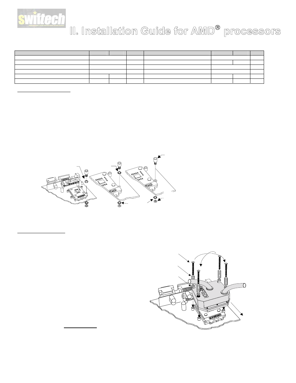
Install standoff in each one of the four holes
surrounding the socket. Keep the standoff &
washer centered over the MB holes, and secure
with a fiber washer and lock-nut on backside of
the MB.
•
Re-install the MB inside the case.
II. Water-block installation
•
The case should be laying flat on a table.
•
Insert the processor into the socket, and lightly coat the
processor core with the included high quality thermal
compound (Arctic Alumina). Only a paper-thin coat is
necessary. It should be applied using preferably a razor blade,
or a credit card, held between thumb and index at a 45-degree
angle. It is critical to ascertain that the entire core is covered
with a uniform coat of thermal compound.
•
Prepare 4 assemblies composed of a 1 ½” screw, 1 nylon
spacer, and 1 spring as shown in Figure 2. Drop each
assembly into the MCW462-U mounting holes.
•
Install the MCW462-U block on the CPU. The copper base of
the MCW462-U features a large step for clearance with the
socket cam box. Make sure to respect this orientation. Keep
the heat sink mounting holes lined up with the standoffs. Avoid
twisting the block to prevent smearing the thermal compound.
•
Gradually tighten the screws in a crisscross pattern until you
feel that they reach the bottom of the standoff. A “finger-tight”
lock is sufficient. Adjustments such as tightening the screws
only partially are strictly prohibited. Such attempts will result
in improper contact between the CPU core and the heat sink,
and result in CPU overheating.
Large step side
over cam box
Crisscros
tightening
pattern
1 1/2“ Philips
screw
Spring
.230x.096
Nylon spacer