Secure the stacking module in place with the fo, Chassis or stacking brackets, In a chassis, place up to six at-mr908tx hubs s – Allied Telesis AT-MR908TX User Manual
Page 37: Figure10: installing stacking brackets, Attach the power cords of all units, Use the scsi ii cable to connect the out port o, Do not match out to out or in to in when connec, Make sure the mdi /mdi-x slide switch on port 1, Repeat the preceding steps until you have conne, Check the front of each hub in the stack to mak
AT-MR908TX Installation Manual
17
4. Secure the stacking module in place with the four screws you removed in
Step 2 above.
Chassis or Stacking Brackets.
You are now ready to connect the AT-MR908TX
hub with another ATMR908TX hub using the SCSI II Stacking cable.
Use the following procedures to connect multiple AT-MR908TX units in a
stacked hub configuration:
1. In a chassis, place up to six AT-MR908TX hubs such that the uplink ports
on the back panel of the units align. Alternately, you can connect two AT-
MR908TX hubs with the stacking brackets included with AT-MR908TX-
19A, AT-MR908TX-29A, and AT-MR908TX-39A models, and with the AT-
MR901 Stacking Module upgrade package. Install the brackets as
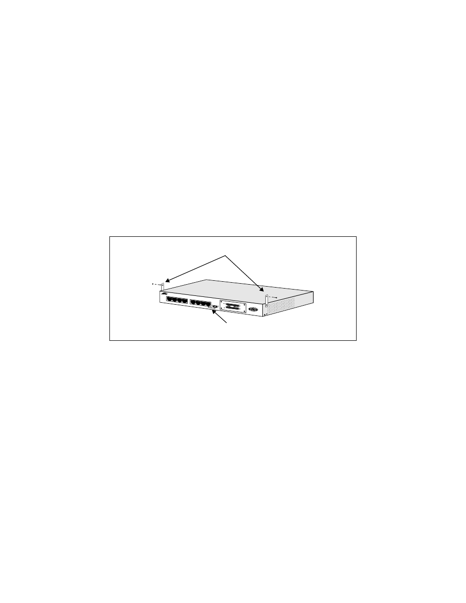
indicated in Figure 10.
Figure 10: Installing Stacking Brackets
2. Attach the power cords of all units.
3. Use the SCSI II cable to connect the OUT port on the bottom unit with the
IN port on the upper unit.
4. Do not match OUT to OUT or IN to IN when connecting the stackable
ports of any pair of hubs.
5. Make sure the MDI /MDI-X slide switch on Port 1 of each hub is set to
MDI-X to use Port 1 for a normal network connection. (See Figure 6 on
page 11.)
6. Repeat the preceding Steps until you have connected up to a maximum of
six AT-MR908 hubs in a single stack
7. Check the front of each hub in the stack to make sure all green power
(PWR) LEDs are illuminated.
Stacking brackets
AT-MR908TX back panel