Table 2: front panel leds, Power (pwr), Green – Allied Telesis AT-MR908TX User Manual
Page 25: Lighted: power on, Unlighted: power off, Collision (col), Amber, Lighted: data collision occurring, Link/activity, Lighted: adapter connected to hub
AT-MR908TX Installation Manual
5
Table 2 details the purpose, color, and functional description of each LED.
Table 2: Front Panel LEDs
Back Panel
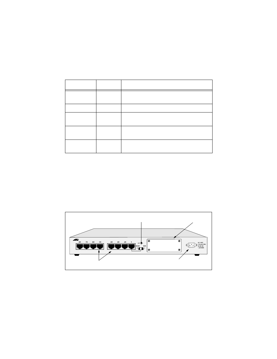
Standalone/Cascade Hub. The back panel of the standalone AT-MR908TX hub is
equipped with a power receptacle, 8 RJ45 ports, and an uplink slide switch
that is defaulted to the MDI-X position for standalone operation.
Models AT-MR908TX-10A, AT-MR908TX-20A or AT-MR908TX-30A have a
blank faceplate. Models AT-MR908TX-19A, AT-MR908TX-29A or
AT-MR908TX-39A include ATI’s AT-MR901 stacking module.
Figure 3: AT-MR908TX Back Panel
LED
Color
Description
Power (PWR)
Green
Lighted: Power on
Unlighted: Power off
Collision (COL)
Amber
Lighted: Data collision occurring
Link/Activity
Green
Lighted: Adapter connected to hub
Flickering: Data receiving
Error
Yellow
Flashing: Data error occurring
Lighted: Partition and isolation of port
Utilization
Green
Hub traffic of the Fast Ethernet bandwidth
(1%, 8%, 16%, 32%, 64%)
blank faceplate
Network ports
Power receptacle
MDI/MDI-X slide switch