Figure2: front panel leds, Light-emitting diodes (leds) – Allied Telesis AT-MR908TX User Manual
Page 24
Product Description
4
Light-emitting Diodes (LEDs)
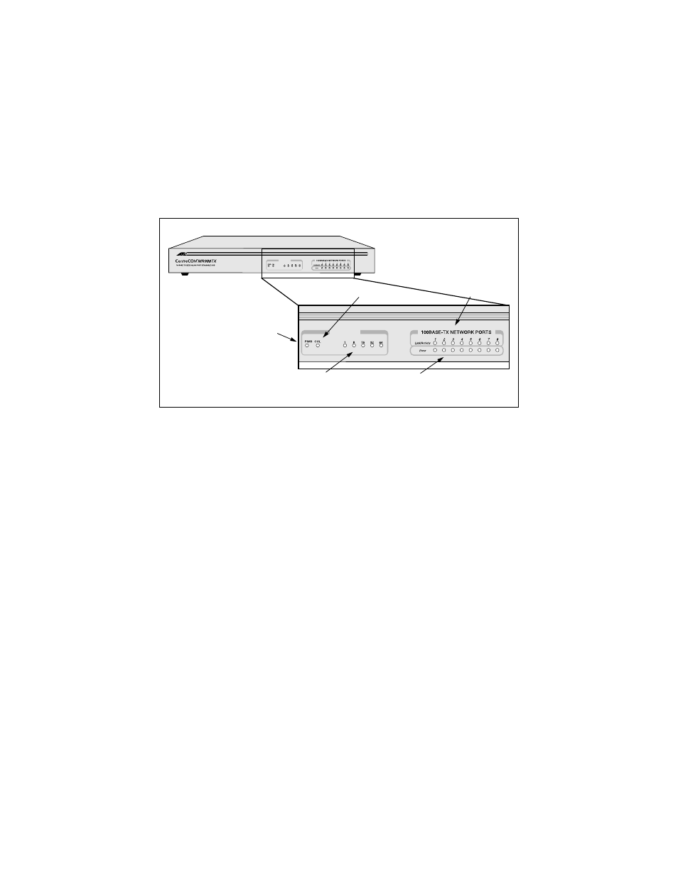
Figure 2 shows the location of the LEDs on the front panel. This faceplate is
common to all AT-MR908TX models.
Figure 2: Front Panel LEDs
An array of light-emitting diodes (LEDs) enable performance monitoring and
failure analysis:
❑
A System Collision LED
❑
A Power LED
❑
Five network Utilization status LEDs
❑
Eight Link/Activity LEDs, one for each RJ45 port
❑
Eight Error detection LEDs, one for each RJ45 port
Front-panel LEDs help you monitor the status of each port. The two parallel
rows of eight Link/Activity LEDs and eight Error LEDs correspond with the 8
shielded RJ-45 ports on the back panel. The five Utilization LEDs indicate hub
traffic within the Fast Ethernet bandwidth. Two additional front panel LEDs
indicate power ON/OFF and collision detection.
Utilization (%)
HUB STATUS
Utilization (%)
HUB STATUS
Power ON/OFF
Utilization
Error Detection
Link/Activity
Collision Detection
- AT-GS908M (54 pages)
- AT-x230-10GP (80 pages)
- AT-GS950/48PS (64 pages)
- AT-GS950/10PS (386 pages)
- AT-GS950/16PS (386 pages)
- AT-GS950/48PS (386 pages)
- AT-9000 Series (258 pages)
- AT-9000 Series (1480 pages)
- IE200 Series (70 pages)
- AT-GS950/48 (378 pages)
- AT-GS950/48 (60 pages)
- AT-GS950/48 (410 pages)
- AT-GS950/8 (52 pages)
- SwitchBlade x8106 (322 pages)
- SwitchBlade x8112 (322 pages)
- SwitchBlade x8106 (240 pages)
- SwitchBlade x8112 (240 pages)
- AT-TQ Series (172 pages)
- AlliedWare Plus Operating System Version 5.4.4C (x310-26FT,x310-26FP,x310-50FT,x310-50FP) (2220 pages)
- FS970M Series (106 pages)
- 8100S Series (140 pages)
- 8100L Series (116 pages)
- x310 Series (116 pages)
- x310 Series (120 pages)
- AT-GS950/16 (44 pages)
- AT-GS950/24 (404 pages)
- AT-GS950/24 (366 pages)
- AT-GS950/16 (404 pages)
- AT-GS950/16 (364 pages)
- AT-GS950/8 (404 pages)
- AT-GS950/8 (364 pages)
- AT-GS950/8 (52 pages)
- AT-8100 Series (330 pages)
- AT-8100 Series (1962 pages)
- AT-FS970M Series (330 pages)
- AT-FS970M Series (1938 pages)
- SwitchBlade x3106 (288 pages)
- SwitchBlade x3112 (294 pages)
- SwitchBlade x3106 (260 pages)
- SwitchBlade x3112 (222 pages)
- AT-S95 CLI (AT-8000GS Series) (397 pages)
- AT-S94 CLI (AT-8000S Series) (402 pages)
- AT-IMC1000T/SFP (23 pages)
- AT-IMC1000TP/SFP (24 pages)
- AT-SBx3106WMB (44 pages)